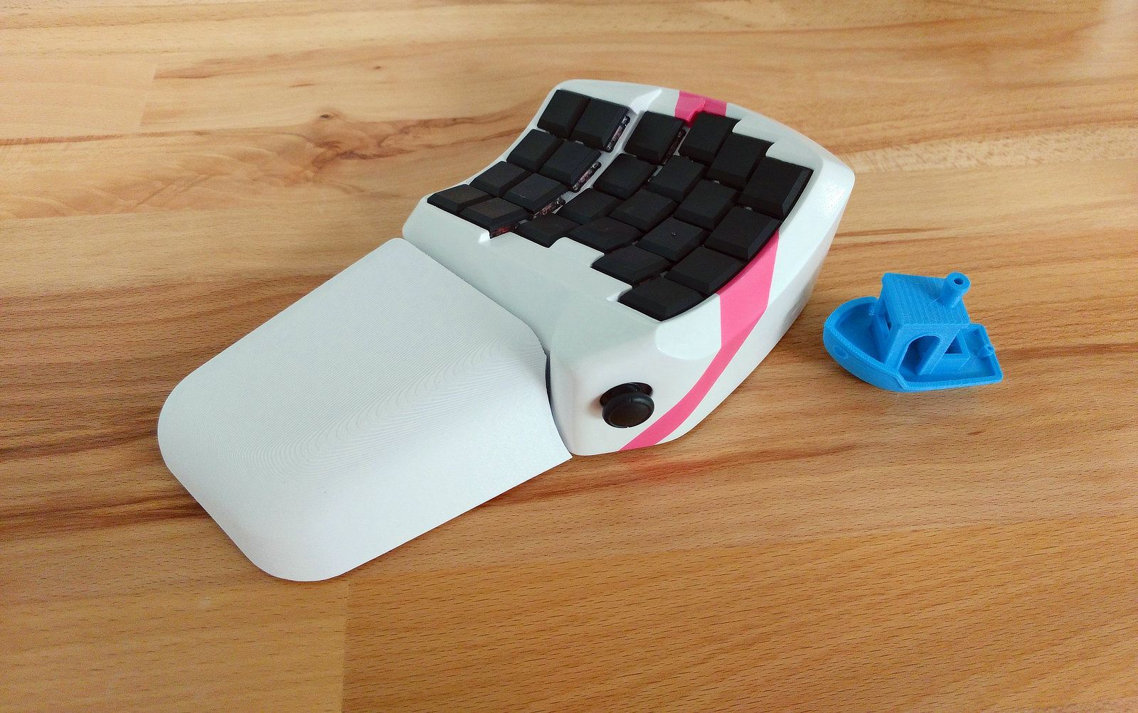
Sherbet gaming keypad
prusaprinters
<p><strong> Warning</strong> I've made a couple of modifications to this since printing <em>and have not tested them</em>. I've added some clearance around the joystick so that it fits better, and the joystick cover now attaches with two screws instead of one. Assembly required filing and cutting in some places to make parts (really just the joystick) fit. I've tried to fix that in later designs but YMMV.</p> <p>I recommend printing individual sections of this design to test for fit prior to printing the whole thing, especially the joystick area, and a keyswitch socket or two.</p> <p>I was not able to get the heat set inserts in the wrist rest to align properly, and will be redesigning it with nuts instead. The joystick is not really usable without a way to keep the keyboard fixed in place, like a wrist rest that's fastened to the case, so this should not be considered ready to use yet.</p> <p><em>I used:</em></p> <ul> <li>24 Kailh choc switches and keycaps</li> <li>24 diodes</li> <li>Third party joycon analog stick replacement. A first-party one ought to work as well.</li> <li>8x screws with threads suitable for plastic, roughly 1.6 - 2mm by about 6mm long, to hold the controller mount, usb breakout, joystick mount and joystick breakout board.</li> <li>6x m3 x 8-10 countersunk screws for the bottom cover.</li> <li>6x m3 heat-set threaded inserts for those screws.</li> <li>2x m4 x 20-25mm cap head screws for wrist rest</li> <li>2x m4 nuts for wrist rest slots (mine were 6.7mm W x 3mm H)</li> <li>uxcell 6pin 0.5mm pitch to dip FFC breakout board.</li> <li>Micro usb breakout module</li> <li>Teensy LC controller</li> <li>As compact and flexible a microusb cable as you can find to connect the controller to the USB breakout board. Case is a bit cramped.</li> <li>Adhesive cork for the bottom</li> <li>Wheel weights to add weight/friction</li> </ul> <p>Build log: <a href="https://www.billiam.org/2019/05/29/sherbet-an-ergonomic-keypad">https://www.billiam.org/2019/05/29/sherbet-an-ergonomic-keypad</a></p> <h3>To-do list</h3> <ul> <li>Done <del>Use different method to secure wrist rest to case. Probably using slots in the bottom and regular m4 nuts.</del></li> <li>Done <del>Cut outs in case lip to fit m4 screw heads (for wrist rest)</del></li> <li>Additional clearance for joystick, maybe</li> </ul> <h3>Updates</h3> <p><strong>2019-07-18</strong></p> <ul> <li>Added wrist rest with slots for captive m4 nuts, instead of heat inserts, which proved to be too hard to insert at the correct angle.</li> <li>Added cutouts to case lip for better m4 screw clearance</li> <li>Reoriented STLs</li> </ul> <p><strong>2019-08-16</strong></p> <ul> <li>Added STEP file</li> </ul> <h3>Print instructions</h3><p>I printed the case with the bottom down, other parts have a natural orientation, except the Teensy mount.</p> <p>I used PrusaSlicer, but the supports were a pain to remove. I think cura and simplify3d may be better. In particular, be careful about supports contacting <em>upper</em> surfaces that may be difficult file, especially where parts fit together. "Support on build plate only" prevents this, but left too many unsupported areas.</p> <h3>Post-processing</h3> <p>I did several layers of alternating filler primer and bond spot putty, followed by rattle can spray primer, and paint. I airbrushed a few coats of Testor's opaque pink for the stripe, and then several gloss clear coats.</p> <p>After those, I sanded with 1200grit to remove some of the orange peel and texture, and then rubbing compound to remove the haze. I recommend also sanding with 2000 before that, but I didn't have any.</p> <h3>Assembly</h3> <p>Insert switches, optionally hot glue these in place if you've done a better job than I did with paint overspray, and your printer has better tolerances.</p> <ol> <li>Use soldering iron and (ideally) special heat-set tip to insert heat-set inserts into holes in bottom of case.</li> <li>Solder matrix rows and columns</li> <li>Solder row and column leads</li> <li>Solder leads to ffc breakout board</li> <li>Insert joystick flex cable into ffc breakout.The cable is 5 pin, while the breakout is 6, so make sure to align to one side or the other, based on which breakout pins you've soldered to.</li> <li>Insert joystick into case, watch orientation so that the ffc isn't crimped, screw on cover. May need to file/sand/carve case and/or joystick, depending on tolerances and support settings.</li> <li>Insert Teensy into Teensy holder mount.</li> <li>Cut USB cable, check length from the location where the USB breakout board mounts to the Teensy. It may be easiest to remove the insulation on the cable so that it's more flexible.</li> <li>Solder USB wires to USB breakout board</li> <li>Mount USB breakout board</li> <li>Remove Teensy from holder. Solder joystick leads to Teensy. Look for diagram online, use voltmeter to verify pins. VCC should go to the 3.3v pin on the Teensy, ground to ground. Analog axes should go to analog pins, joystick button to a regular digital pin.</li> <li>Solder row and column leads to Teensy.</li> <li>Put Teensy back in holder. Optionally hotglue to holder. Attach holder to side of case.</li> <li>Cut cork, stick to case cover</li> <li>Use m4 screws and nuts in wrist rest slots to attach wrist rest to case.</li> <li>Flash Teensy with your keyboard configuration. Here's the arduino sketch I put together: <a href="https://gist.github.com/Billiam/ec4ccf967088edef36e67010839f3dd1">https://gist.github.com/Billiam/ec4ccf967088edef36e67010839f3dd1</a>, or use TMK/QMK or whatever you like.</li> <li>Screw on case cover</li> </ol>
With this file you will be able to print Sherbet gaming keypad with your 3D printer. Click on the button and save the file on your computer to work, edit or customize your design. You can also find more 3D designs for printers on Sherbet gaming keypad.
