Sharpiener: Parametric & magnetizable marker stand
prusaprinters
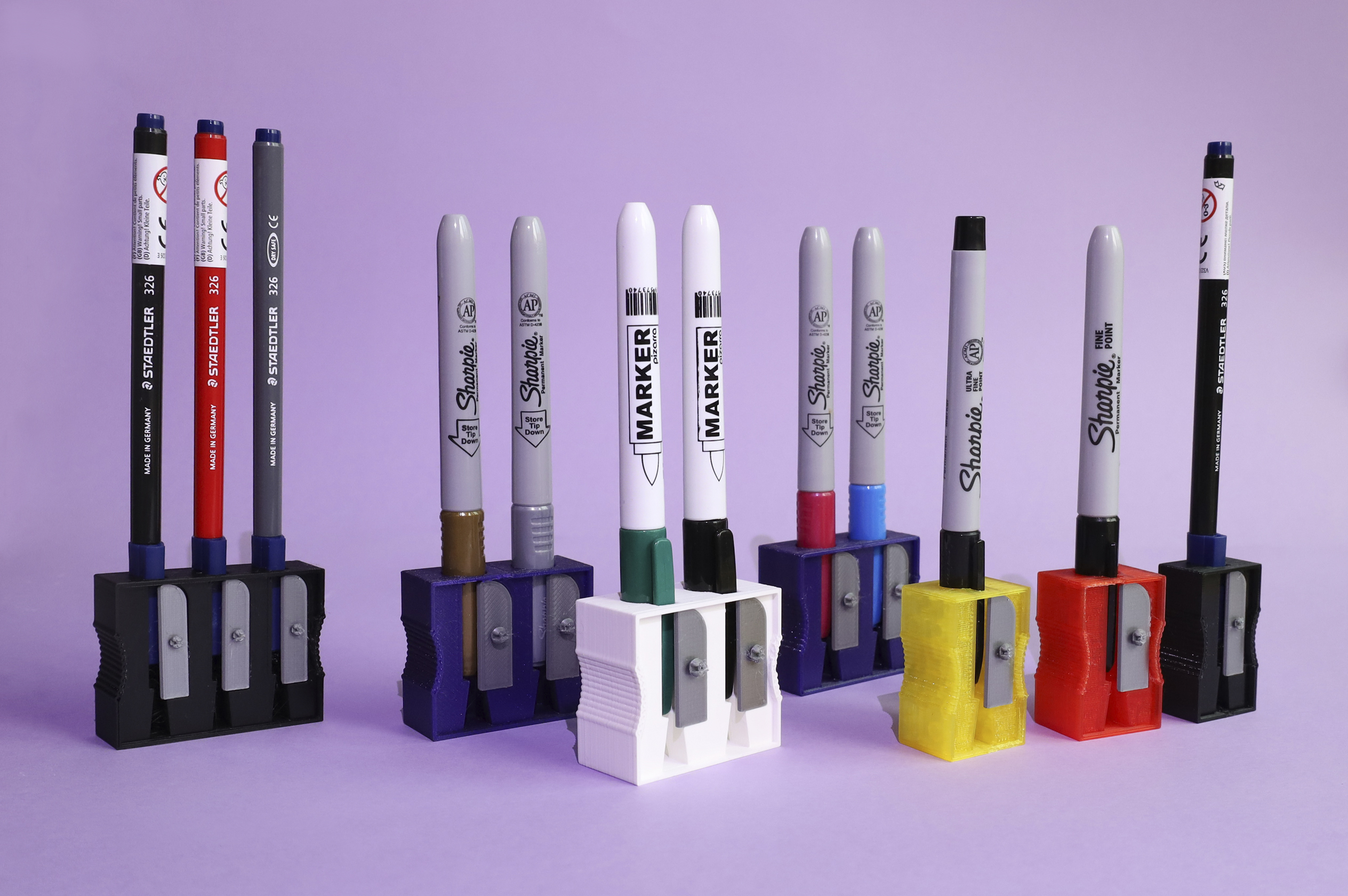
<p>You don't need to sharpen a Sharpie, that's true. But metallic markers are required to be stored point-down; and it's always useful to have a magnetic stand for your hanging whiteboard markers. That's when the Sharpiener comes into use!</p><p>There are STLS included for several types of markers: metallic, fine-point and ultrafine-point Sharpies, Staedtler 326, some dollar-store (well, euro-store) whiteboard markers... but you can make your own Sharpiener with the included .scad file. *You don't need to know how to code in OpenSCAD*, you'll just need to enter values and move sliders, press F6 then F7, and you're good to go! (Refer to the bundled PDF "Using OpenSCAD customizer" for a longer, more detailed explanation).</p><h3>INSTALLING THE CUSTOMIZER</h3><p>To use the customizer, you must have OpenSCAD installed (see <a href="https://openscad.org/downloads.html">OpenSCAD downloads page</a>). Download the file <strong>Marker_stand.scad</strong> and put it in any folder you want.</p><p>Download also the file <strong>Marker_stand.txt</strong>, put it in that same folder, and change its extension to .json instead of .txt. Or, alternatively, download <strong>Marker_stand_json</strong>.<strong>zip </strong>and extract it in that folder. This txt/zip file is the file with the presets, so you can modify them easily. Unfortunately, right now Printables doesn't support uploading JSON files straight away, so you have to either modify the extension manually or use the zip workaround.</p><p>You're now all set and ready to go; simply open Marker_stand.scad and start playing! You can (and should) ignore the "Editor" window at the left, and focus on the "Customizer" window at the right; if you can't see it, go to the OpenSCAD menu Window->Hide Customizer and uncheck it. </p><h3>CUSTOMIZER PARAMETERS</h3><p>As you can see in the pictures, a Sharpiener can have one or more holes or "modules", holding one or more markers. So there are a first, global set of parameters, another for the module specifications, another for the magnet specifications (if any), and another for the optional recycling symbol.</p><h4>MAIN PARAMETERS</h4><p>This set of parameters affect the whole Sharpiener:</p><ul><li><strong>Object type</strong>: There are two or three parts to be printed separately in a Sharpiener: the main stand, the blade(s) and, if you use the print-on-print technique, the recycling symbol. Here you choose which one will be generated.</li><li><strong>Modules</strong>: How many markers the stand will hold (i.e., how many modules).</li><li><strong>Wall thickness</strong>: The Sharpiener modules are surrounded by a "wall", that usually will protrude from the module top face, to make room for the blade "screw" but also to give a greater footprint (and more stability). This ideally should be such as to print with an integer number of perimeters. E.gr., the default is 1.27, which comes to be about 2 perimeters with a 0.6 nozzle and 3 perimeters with a 0.4. You can check the recommended thin wall thickness for your setup (it's in the slicer) to make it nice. Set the wall thickness to 0 to disable the wall.</li><li><strong>Wall height</strong>: The height of the wall above the topmost surface of the Sharpiener (not counting the blade). You can set this to 0, but then the wall won't be disabled.</li><li><strong>Precision</strong>: How many segments there are in a full circle. A higher value gives much smoother rounded shapes, but takes longer to render with F6 and gives a higher sized file (it's a high-poly model, after all).</li></ul><h4>MARKER DIMENSIONS</h4><p>The marker characteristics, dimensions (and spacing) will determine the characteristics of each module (all will be identical), so likely this is the most important section. Something of note: the Y and Z axis will be swapped from printing orientation (blade up) to the stand stance (blade in front), so "front" and "top" may be a little confusing for a while. So the parameters are mostly defined taking as a reference the marker well and hole, which are on top in standing position and in front when printing/creating the model.</p><ul><li><strong>Marker diameter</strong>: This is the maximum diameter of the marker or Sharpie. Note that many markers have tapered caps, so measure either at the length of insertion or at their maximum value.</li><li><strong>Marker clearance</strong>: It's good to have a bit of wiggle room to pick/put the marker easily in the Sharpiener. A value of 0.2 will usually do well, and possibly compensate for any tidbits on measuring the diameter.</li><li><strong>Marker cap tab width</strong> and <strong>Marker cap tab depth</strong>: Many markers have a tab so you can put them in your pocket. If that's the case, we need something of a "keyhole" profile; these two variables control the square part of the keyhole. Width is the length along the X axis; depth is along Z/Y axes (remember the orientation thing we talked about), which is how much does the tab protrude from the marker cap, in protruding-from-your-pocket direction. Set any of these to 0 to disable the cap tab notch.</li><li><strong>Marker hole depth</strong>: How deep is the well to put the marker in. In printing position is along Y axis, in standing position is along Z.</li><li><strong>Marker hole depth margin</strong>: This is an extra space beyond the marker well, both for aesthetics and functional purposes; this will add extra material to the base when standing up, adding extra stability. So, this is the distance between the well end and the side opposite to that of the hole. For nice looks, it's good if it's around 1/2 the depth of the wall, but YMMV.</li><li><strong>Marker hole vertical margin</strong>: This is the spacing for the wall in Z-axis when printing/creating, and Y-axis when standing. That is, the distance between the well and blade, and well and side opposite to that of the blade, not counting magnet spaces (if any) nor the blade itself, nor the wall height (if any).</li><li><strong>Marker hole horizontal margin</strong>: Margin along the X axis. This, plus marker diameter and clearance, will determine the module width.</li></ul><h4>MAGNET DIMENSIONS</h4><p>Magnet holes are added to the whole of the Sharpiener, not per module. Remember to add the pause in the slicer, and a dab of strong glue when printing, if you're using magnets.</p><ul><li><strong>Magnet shape</strong>. Set to "None" if you don't want the magnet space. Otherwise, choose between round/cylindrical and square/rectangular.</li><li><strong>Magnet width</strong>. This is the length across the X axis for square/rectangular magnets, or diameter for round/cylindrical magnets.</li><li><strong>Magnet depth</strong>. Length across the Y axis (printing orientation) for square/rectangular magnets, unused for round/cylindrical magnets.</li><li><strong>Magnet height</strong>. Length across the Z axis (printing orientation) for all types of magnets, which will be the Y axis in standing position.</li><li><strong>Magnet clearance</strong>. A bit of extra space so the magnet isn't supertight. Or maybe it is, if you set this to 0... Note that this is the same value for all axes.</li><li><strong>Magnet spacing</strong>. Distance between the magnet area and the model floor (in printing orientation)/back (standing position). The distance from the magnet area to the marker well is still determined by the Marker hole vertical margin parameter.</li></ul><h4>RECYCLING SYMBOL</h4><p>You may add a recycling symbol to your Sharpiener, but you'll need to have installed the <a href="https://www.printables.com/model/136201-recymbol-customizable-recycling-symbols-and-librar">Recymbol library</a>. If you don't have it installed, the customizer will throw some minor errors and the symbol won't be available, but that's all. To install the library, just <a href="https://www.printables.com/model/136201-recymbol-customizable-recycling-symbols-and-librar">download the file from here</a>, open your OpenSCAD library folder (go to File->Open library folder in OpenSCAD), create a folder named "Recymbol" there, and drop inside it the library.scad file. That's all, and you'll have it installed across all your OpenSCAD customizers and files. <br>The Recymbol library version used is 1.1 (published 2022-08-07); if you're using an earlier version, there will be another noncritical error and one of the parameters won't have any effect, but other than that the symbol will be created properly.</p><p>Symbol parameters are:</p><ul><li><strong>Material</strong>: Set to “none” to disable the symbol. If the material is not listed, select "Other material" (last option) and fill it in the "Custom material type" parameter box. Code will be 92 if it's a composite (starting by C/, like C/PP) or 7 otherwise.</li><li><strong>Symbol font</strong>: Font to use in the symbol; use OpenSCAD nomenclature. You can copy and paste from OpenSCAD's font list, removing the quotes. See the bundled "Using OpenSCAD customizer" PDF for more details.</li><li><strong>Recycling symbol offset</strong>: An extra thickening (positive offset) or thinning (negative offset) of all the symbol, to aid in 3D printing. Usually you won't need to add any value, unless the symbol ends up being really small.</li><li><strong>Recycling symbol text offset</strong>: As the above parameter, but only applied to the material abbreviation; it's usually the part that gives most trouble when printing, as it's smaller than the code and the arrows and maybe there aren't enough perimeters to it to give a clear model. This is the only parameter requiring Recymbol version 1.1 or higher (at the time of writing this, 1.1 is the newest version).</li><li><strong>Symbol style</strong>: How the symbol will be applied. “Print-on-print” usually gives the best results, as it can be printed in a different color for greater clarity, but requires a bit more work. "Engraved" is simply the symbol cut out from the base. In "Stacked" style, the symbol is also engraved, but in a "stepped" way, thinning it at each layer so the section is a 45-degree shape. You can also add a z-based color change with this style for better clarity.</li><li><strong>Symbol depth</strong>: Not used in print-on-print, this determines either the depth of the engraving in the "Engraved" style, or the height of the full, first part of the symbol in the "Stacked" style.</li><li><strong>Symbol precision</strong>: Much like the "Precision" main parameter, but only for the recycling symbol. A higher value will give a much smoother text, but will take more to render, especially with the "Stacked" style.</li></ul><h5>USING THE PRINT-ON-PRINT TECHNIQUE</h5><p>To use a print-on-print symbol:</p><ol><li>Generate both the symbol, main Sharpiener body and blade.</li><li>Load in the slicer the symbol and main body, and check that they fit right.</li><li>Set the main body as non-printable (in PrusaSlicer, click the eye icon next to the model name), and slice and save the symbol.</li><li>Next, set the symbol as non-printable, the main body as printable and slice and save the sliced file.</li><li>Print the symbol. Remove the purge line and skirt.</li><li>Preheat and change the filament. Let it wait and "bake" for a little bit until it doesn't drip anymore, and remove it from the nozzle with a pair of tweezers. This is because in the leveling bed routine, any bit of plastic from the nozzle could deposit over the printed symbol, which could potentially lead to a crash and stripping the printed symbol from the bed.</li><li>Now print normally the model.</li></ol><h3>TIPS AND TRICKS</h3><p>Which magnet you need will depend, first, on the availability (supply chain problems and so), and which ones you do have at hand. On a thin sheet like a whiteboard, a 10x2 round magnet holds well a single-module Sharpiener, but struggles a bit with two modules; on a thicker metal sheet like a You can place more than one round magnet with this simple trick: set to square shape, with width and depth of the bounding box of your round magnet disposition. So, if you want to put two 10-diameter round magnets side-by-side, just set the square shape to 20x10.</p><p>You can also put the magnets so the Sharpieners hold well back to back; just check the polarities. You can start by making one Sharpiener, put the other magnet(s) on it, and mark which side will go "up" in the print. You can use a Sharpie :).</p><p>You can make a toolhead by removing the walls (make them 0 thickness or height), including a magnet, and leaving a short "marker depth margin"; use a very small clearance (even 0) and a tight measurement of the marker diameter for a strong hold (even a mallet-needed-to-insert-marker-tight hold).</p><p>*Remember* to always add a dab of glue before putting the magnet, and to add the pause in the slicer! Also, if in doubt, remember that the "pause" command is *after* layer change, but *before* printing of that layer starts; so add it in the first layer covering the hole.</p><h3>FINAL WARNING</h3><p>If you use the dimensions of a pencil and are careful with the printing settings, the Sharpiener may pass as a regular, run-of-the mill office sharpener. We're not saying that you could (or should) use it for pranks.</p><p>We're not saying otherwise, either. We're... just sayin'.</p><p>And that's all! Have fun non-sharpening your Sharpies!!</p>
With this file you will be able to print Sharpiener: Parametric & magnetizable marker stand with your 3D printer. Click on the button and save the file on your computer to work, edit or customize your design. You can also find more 3D designs for printers on Sharpiener: Parametric & magnetizable marker stand.