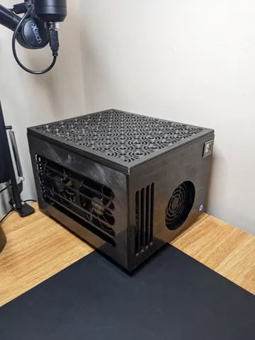
SFF ITX PC Case
prusaprinters
There are probably some odd things that I missed during my many edits and revisions of this case. I'll try to cover everything below, but feel free to ask if there's anything weird.Description:This is a case that I designed to keep a small form factor pc on my home office desk. The case has a horizontal motherboard with gpu attached directly, and a sfx PSU in front. The PSU and GPU cables face up, making the case height limiter the cables coming out of those components (as seen in some of the pictures). It allows for about 140mm height for a cpu cooler, but that can be adjusted by designing a taller top frame or just cutting a hole in the top hot-rod style. In my case, I have a C-shaped Noctua nh-c14s cooler which barely fits with the stock fan on top (though I have it underneath the radiator now).pc specs in pictures: AMD 5600x cpu, Radeon RX 6700XT gpu, EVGA SuperNOVA 650 GM psu, noctua nh-c14s cpu coolerPrinting instructions:To print this, print:1 front, back, left, right, bottom panel1 top frame out of the two optionsThis depends on personal preference and cpu cooler height. The double support looks more symmetrical, but I had to design the single support to fit the noctua cooler with a fan above.1 top panel out of the 3 optionsTotally personal preference. The circle one looks cool but takes a while to print. The “CashinChecks'” one was sort of designed as a joke, but I think it's great. For any that don't get the Stepbrothers reference: https://www.youtube.com/watch?v=FsIecUNubUA 5 Feet1 gpuLock From the way I printed this I think it took about 500g of filament, but I don't remember exactly. I printed in PETG and would recommend something other than PLA to ensure there's no warping at high temps. I think it should be fairly obvious which way to print each piece when viewing the models, usually it's the outside of the case flat against the print bed. This way the internal mounts can stick up. Then just assemble. Sand and repaint if you want, I didn't do anything like that on mine.Assembly:BottomPlatform: heat insert in each of the 5 foot holes, they're the holes set in a bit more from the edge and one in the middle. There will be 8 other holes for screws to go up into the side panels. I made the motherboard pilllars just screw into plastic instead of heat inserts (just in case the motherboard screws had different threads or something…wasn't sure at the time). If you print it with like 3 walls, these will have plenty of holding strength.FrontPanel: put a heat insert into all 4 places where the right/left panels connect to the front panel. These need to be screwed together from the inside before the GPU is put into the case, so keep that in mind. Heat inserts are also needed where the top and bottom panels attach. For the bottom panel corner connections, there isn't much plastic there. It will deform when you try to do this, but just hold it as best you can. Mine were deformed a bit but good enough to hold it in place.BackPanel: same heat inserts as the front panel for the top and bottom, but the connections to the left/right panels are through holes on these, not heat inserts. The heat inserts go on the left/right panels which come next. 2 M2 inserts are needed for the gpu lock to screw into.gpuLock: Look at the picture of the GPU lock model; the m3 inserts go into the top so the gpu can screw in from above. Then the M2 screws go into the sides to screw into the backPanel.Left/Right Panel: Heat inserts on the top to attach the top frame, just like the other panels. One heat insert on the bottom middle for the bottomPlatform to screw up into. The bottom corners slide between the back/front panel and the bottomPlatform. Screw through the holes into the frontPanel heat inserts.I just noticed that the rightPanel still has and extra connection in the middle of the backPanel from a previous iteration. Just chop it off after printing.TopFrame: just screw down using M3 screws into the side/front/back panels.TopPanel. This just fits down into the topFrame using the pegs/holes in the corners . This allows a clean top panel without screw holes, and allows faster switching if you want to change top panel design/color more often. Hardware required/recommended:power switch: any 12mm power switch will work. I got this one because it has the LED as well: https://www.amazon.com/gp/product/B095S85PZQ/ref=ppx_yo_dt_b_search_asin_title?ie=UTF8&psc=1M3 heat inserts: I think this uses 22 of these. I got this and had plenty to spare: https://www.amazon.com/gp/product/B07D683Q26/ref=ppx_yo_dt_b_search_asin_title?ie=UTF8&psc=1 . You'll need to get the 3mm deep ones to make a couple of them work, but most would be fine with 5mm deep or more if that's what is available.M3 screws: I had an assortment of these already, but used about 22 of these between 5mm and 8mm long. This kit would cover it I think: https://www.amazon.com/gp/product/B07CYNKLT2/ref=ppx_yo_dt_b_search_asin_title?ie=UTF8&psc=1 M2 heat inserts: need 2 of these for the gpu lock on the back panel. I had some laying around, but something like this would work: https://www.amazon.com/dp/B09ZNG1V6T?ref_=cm_sw_r_cp_ud_dp_1CYY4XAWW0C094B51MZC M2 screws: just need 2 for the gpu lock. Something like 10 or 12mm would do. This set would have what's needed for sure: https://www.amazon.com/gp/product/B07W6GMK58/ref=ppx_yo_dt_b_search_asin_title?psc=1&ref_=cm_sw_r_cp_ud_dp_567RZQ58PEX1SJ197M50 Motherboard screws: just use whatever you had before, or what was provided with your motherboard
With this file you will be able to print SFF ITX PC Case with your 3D printer. Click on the button and save the file on your computer to work, edit or customize your design. You can also find more 3D designs for printers on SFF ITX PC Case.
