SEPARATOR - air purification system for Voron 2.4
prusaprinters
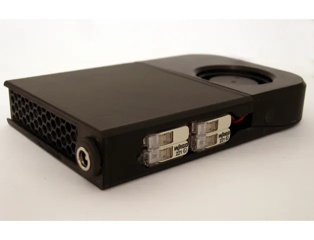
UPDATE KPrevious versions are clashing with the kinematic mount mod from whopping_Voron_mods (https://github.com/tanaes/whopping_Voron_mods/tree/main/kinematic_bed) as the modules have a height of 21 mm. V1.5K (modified microfit connector) and V2K (barrel plug) are modified versions to make the Separator compatible with this kinematic mount. While the parts differ slightly V2K is still assembled like V2 and V1.5K like V1.5, as described in the assembly instructions. UPDATE V2 V2 adds the option of using barrel plugs as connector system. The used connector is rated for much higher mating cycles (5000) than microfit (250 if lubricated crimp contacts are used). The instructions describe this new and the old version with modified microfit connector. Make sure to use the connector from the BOM, as many other barrel plugs are not rated for sufficiently high voltage or sufficiently high temperature. UPDATE V1.5 V1.5 combines the modified Microfit connector system with Wagos for easy, crimping free exchange of fans or exchange of the microfit connector without the need to shorten the fan cables in the process. For the Dual Module the WAGOs are also an easy, soldering free option to combine the cables from both fans.________________________________________________________________________________________________________________ AIMReduction of volatile organic compounds (VOCs) in the Voron 2.4 enclosure via circulatory active carbon filtration combined with forced air circulation below the print bed to speed up and enhance passive heating of the enclosure.With an optional add-on, the system also uses particle filtration to purify the air and air circulation in the chamber is further improved: https://www.printables.com/model/624105-separator-particle-filter-for-voron-24 IntroductionThis air filtration system is inspired by the popular Nevermore system, by The_Filter as well as Ellis' bed fan mod, but designed from scratch with a number of key differences. (https://github.com/nevermore3d/Nevermore_Micro/tree/master/V6, https://github.com/nateb16/VoronUsers/tree/master/printer_mods/nateb16/THE_FILTER, https://github.com/VoronDesign/VoronUsers/tree/master/printer_mods/Ellis/Bed_Fans) Key features it shares with The_Filter but which differ from the Nevermore system:The airflow is reversed so that air is not blown directly at the weak link of the enclosure (the door) and a design for 4 blowers to improve ventillation below the heatbed, for better and faster heating of the enclosure. Key features unique to the “Separator”:The blowers are fully embedded in a dampening EPDM layer. Vibration noise is a major component of fan noise, especially for blowers. This substantially reduces the transmission of vibrations into the filter body.Inlet and outlet mesh of the filter module is as slim as possible with the least air resistance in mind, while containing the activated charcoal pellets (diameter: >4 mm) and featuring the needed stability.The filtration cassette is from one piece and (re-)filled vertically. This enables filling with smaller air gap at the top.The filtration cassette is gap free, except for the outlet and the interface to the blowers, which is sealed by EPDM, to maintain the positive pressure better within the cassette.Like "The_Filter" the "Separator" is designed in a way that blowers are removed with the cassette when refilling AC pellets, but the "Separator" has an entirely different connector strategy.DISCLAIMER: This design uses barrel connectors or non-spec Micro-Fit 3.0 connectors. Use at your own risk. Print AdviceThe mesh of the mesh parts is created in the slicer via modifier volume with the following settings: (tested in Prusa Slicer):Infill angle: 0°Infill type: honeycombInfill percentage: 16%Perimeters: 0Top layer: 0Bottom layers: 0If the object is turned the mesh doesn't turn with it but the infill angle has to be adjusted by the same angle ans the object rotation. If the mesh is too coarse for your active carbon pellets, increase the infill percentage as needed for a finer mesh. BOMNeeded parts for a full setup with one central "dual"-module and a "single-left" as well as a "single-right" module. 4x 5015 high performance blower (24V), for example https://en.kris3d.de/products/gdstime-gdb5015-50x50x15mm-blower-fan?_pos=3&_sid=fd8a2629a&_ss=ractive carbon, suitable for air purification, a safe bet is the nevermore material (https://www.kris3d.de/products/nevermore-xl-bag?_pos=2&_sid=f7ffb3feb&_ss=r), alternatively source equivalent material from a respectable source.a few meters of 2mm thick and 10 mm wide EPDM tape or similar (for example: https://www.fugendichtband24.de/EPDM-Zellkautschuk-einseitig-selbstklebend-10m-Rolle-2mm-x-diverse-Breiten.htm; Alternative Source: https://www.aliexpress.us/item/3256805407758122.html)a few meters of >0.25 mm2 cable for cable management, preferably Heluflon or equivalent due to the very high heat resistanceScrews, nuts and magnets13x M3x6mm countersunk head cap screws DIN799118-21x M3x6mm button head screws ISO 7380-16x M2x4mm button head screws ISO7380-1 (compatible hex-key (1.27mm or 0.05"): https://www.digikey.at/de/products/detail/wiha/66945/511457))31x M3 Voron style heat inserts (M3x5x4) (https://www.kris3d.de/products/heatinserts-m3x5x4?_pos=1&_sid=886fd1c22&_ss=r)6x M2 heat inserts (https://cnckitchen.store/products/gewindeeinsatz-threaded-insert-m2-standard-100-stk-pcs) 6-9xM3 t-nut ((https://www.kris3d.de/products/ldo-m3-nutensteine?_pos=1&_sid=f968a320c&_ss=r))8-14x magnets (6mm diameter, depth: 3 mm) preferably high temperature variants like N35H (https://fermio.xyz/fermio-labs-gmbh/round-neodym-magnets-6-x-3-mm-n35h-high-temp-electrically-conductive/) Option V2: Barrel connector 3x Tensility art. no. 10-02321: 2.5mm ID, 5.5mm OD Plug, rated for 48V, 4.8A, Max ambient temperature 105°C (https://www.digikey.at/de/products/detail/tensility-international-corp/10-02321/7087230), part B is designed for this specific plug. Alternatives: https://www.digikey.at/en/products/detail/tensility-international-corp/10-02316/7087225, https://www.digikey.at/en/products/detail/tensility-international-corp/10-03131/97610553x Tensility art. no. 10-03610: 2.5mm ID, 5.5mm OD Jack, rated for 48V, 6.0A, Max ambient temperature 105°C (https://www.digikey.at/en/products/detail/tensility-international-corp/10-03610/12090913), part A is designed for this specific Jack. Optional: 8x WAGO 221-482, max ambient temperature 105°C (https://www.digikey.at/en/products/detail/wago-corporation/221-482/15528530)If the above plug or jack is not available this alternative plug/jack pair should work as well, instead of the above plug and jack:3x Tensility art. no. 10-02317: 2.1mm ID, 5.5mm OD Plug, rated for 48V, 4.8A, Max ambient temperature 105°C (https://www.digikey.at/en/products/detail/tensility-international-corp/10-02317/7087226), Alternatives: https://www.digikey.at/en/products/detail/tensility-international-corp/10-02318/7087227, https://www.digikey.at/en/products/detail/tensility-international-corp/10-03130/97610543x Tensility art. no. 10-03609: 2.1mm ID, 5.5mm OD Jack, rated for 48V, 7.5A, Max ambient temperature 105°C (https://www.digikey.at/en/products/detail/tensility-international-corp/10-03609/12090912) Option V1: Microfit based Connector3x MOLEX Microfit 3.0 connector part Nr. 0430200201 (https://www.digikey.at/de/products/detail/molex/0430200201/1132437)3x MOLEX Microfit 3.0 connector part Nr. 0430250208 (https://www.digikey.at/de/products/detail/molex/0430250208/4247397)6x MOLEX crimping contacts part Nr. 0462355002 (add some spares, according to your crimping skills), IMPORTANT: buy those lubricated crimping contacts which are rated for 250 mating cycles, others are rated for no more than 30 mating cycles6x MOLEX crimping contacts part Nr. 0430310009 (add some spares, according to your crimping skills) IMPORTANT: buy the gold plated contact for higher durability Optional cable management2x WAGO 221-2411 or 2x WAGO 221-482 AssemblyOnly for Option V1 and V1.5: Preparation of Microfit connectorPrepare MOLEX Micro-fit 3.0 connectors by removing the snap connection points with a cutter, so that the surface is flush afterwards, as shown in the below before and after image:Test assemble the Microfit 3.0 connectors as shown in the two following images. Be careful of the precise orientation.Test the connection of both parts, they should easily slide into each other. If they don't one of the connectors is either upside down or there is some printing artifact which needs to be cleared by cutter. The connection should look like this:Disassemble the connectors and remove the micro-fit 3.0 plugs from the printed parts again.Assembly for V1, V1.5 and V2Install the bottom mesh in partA (V1: same mesh is used for top and bottom, V2 and V1.5: MeshB is used for bottom) by sliding it in while keeping it tilted until the intentation in the filter body, press the mesh then past the holding protrusions. Use some Hexkey if your fingers don't make it as far. If the tolerances are too tight, one can simply print a rescalee mesh. The rescaling can be done directly in the slicer (eg. -200 µm in X and Y dimension). The mesh should be printed in ABS for having the necessary flexibility.Check if the mesh is fully clipped in as seen here:Add M3 heat inserts to the back of partA.Screw together PartA and PartC with 4 M3x6 button head screws.Apply EPDM tape (thickness: 2mm) as shown. The blower inlet is prepared with EPDM tape on all sides, make sure that on the other side, those strips only reach as far as the opening and not further.Add M3 heat inserts and EPDM tape to partD as shown. Cut the 10 mm tape in half to a width of 5 mm and apply it ring shaped around the opening. Along the vertical wall apply the 10 mm tape centrally.Insert the blower in PartD by wiggling it in, make sure not to push the tape down and direct the cable to the opening.Combine partA+C and partD. Make sure not to clamp in cable or other parts or cause some EPDM tape overlap. There should be only slight backpressure when screwing it together. Keep both parts together with one hand and fasten 3Mx6mm countersunk head cap screws with the other hand. The cable has to be lead through the opening on the side and has to be routed to the front where the connector will be located. Insert the 6 mm magnets into the holes after making sure that there are no bulges from the heatsets or other artifacts blocking the opening. Test fit the magnet and see if it fully goes in. If it holds by itself, fine, if not use a tiny drop of superglue at the bottom to glue the magnet in place. When inserting magnets make sure that the counterpart is inserted in the right direction, that it attracts the other magnet.V1: Shorten the cables as needed, crimp them, assemble the connector and insert it in place. For the dual module the cables from the two fans can be either connected by soldering or by choosing V1.5 with WAGO clamps. V2: Remove washer and nut from the Jack and screw it into the front thread. Shorten jack cables and fan cables as needed and connect them. This can be done with two Wagos 221-482 which fit into the side cavity. If the Wagos sit too loose, add some insulation tape to one side wall until the fit is tight. Repeat the assembly for all modules and fill the filter with active carbon. The filter cassette is closed by sliding a mesh in place at the end of the module (V2: MeshA). Completed module V2 Completed module V1 Installing modules in a Voron 2.4Add M2 heat inserts to the profile magnet holders. There are two different versions in the STL folder. Use the flush ones. For the dual module in the center one can use the "+1mm" magnet holder on the right side if there is too much play with the dual module between both profiles.Turn around the magnet holder and check if plastic debris is blocking the heat insert. If so clear it with a fine cutter knife.Insert a 6mm magnet in the central hole and make sure it is point the right way so that it attracts the counterpart on the respective module.The maget holders are then installed in the profile by first pushing in the side parts and in between the magnet holder as shown in the image below:Subsequently move the 3 parts together and to the very front. Add M2 button head screws and fasten the screws just enough to fix the maget holder in place. Don't overtighten.V1+V1.5: Assemble partB. Crimp the Microfit connector and insert it in part B. Add the magnet in the central hole. Make sure it is oriented the correct way.One magnet holder goes into each side of both bed profiles on the front side, four in total. Test install each module. When a module is pulled in place by the profile magnet it is time to install part B at the profile. Two M3 T-nuts are inserted (with the two wholes close to each other), loosely screw partB to the T-nuts and move it forward to the module until the microfit connnection is closed. Fasten partB in the orientation where the connection is aligned.V2: Insert the plug into partB-V2.Two or three M3 T-nuts are inserted (depending on the choice of partB-V2, either with 2 or three screw holes). If space allows the three screw hole version is recommended. Plug in the plug+partB-V2 into the jack of the module which is in place and aligned to the magnet in the profile. Screw down part B in this alignment by tightening the1-2 accessible screws. Remove the plug afterwards and screw tight the additional screw and reinsert the plug aftwards. Optional: 2 WAGO clamps can be mounted sideways with the WAGO clamp mount and the 3 positive cables go to one clamp and the 3 negative cables to the other clamp. The other side is connected to a 24V fan control pin or the 24V hotendheater outlet. WAGO clamp mounts for two 221-482 and 221-2411 are available. V2: Final assembly with a left and right single module and a dual moduleV1+V1.5: Final assembly with a left and right single module and a dual moduleV2: Removing modulesThe barrel plug connection has a firm grip. Removing modules works well but one needs to have the right technique. Use the fan opening of the exterior to grip the module while holding it with the other hand down and for the single modules also on the side to create a horizontal outwards pull. Pull slowly.
With this file you will be able to print SEPARATOR - air purification system for Voron 2.4 with your 3D printer. Click on the button and save the file on your computer to work, edit or customize your design. You can also find more 3D designs for printers on SEPARATOR - air purification system for Voron 2.4.