 thingiverse
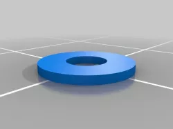
ScrewsMetric
The STLs given are not printable, and are simply demos of what the library can produce.
Files are available on [github](https://github.com/More-Wrong/ScrewsMetric).
They aren't here because thingiverse doesn't support folders.
ScrewsMetric
============
## What is it?
ScrewsMetric is an OpenSCAD library that helps you embed precisely-defined bolts, nuts, washers, and bearings in your designs. It provides a
massive database of values for dimensions of standard parts, and is designed with several goals in mind:
- To allow easy access to the dimensions of standard hardware
- To allow the easy interchanging of equivalent parts, without adjusting many variables (e.g. changing button-head bolts to counter-sunk)
- To allow rendering of parts for mock-up with little difficulty
- To make code more readable
This help file lists all the important elements of ScrewsMetric.
In order to get a good feel for the system however, I would recommend playing with it - running the demos, and trying your own thing.
The system tries to output all needed information in echo statements, but this isn't everything,
and is more intended for easy copy and paste of variables (typing `getHeadDiameter` gets boring very quickly).
ScrewsMetric was originally a simple database, only supporting a few types of metric bolt and basic nuts, with no modules attached.
Over time it gained functionality, up to now, where it provides several layers of abstraction.
ScrewsMetric is for metric bolts, but there is another version (currently work in progress) which should work for imperial, called ScrewsUNC.
To allow both UNC and Metric bolts to exist at the same time, there is also ScrewsUniversal, however to properly allow interchangeability, only the high level functions and modules should be used as described below.
This allows ScrewsUniversal to make switching between Metric and UNC components easy.
## Getting started
First download the library, unzip it as necessary, and place all the contents in a work directory.
To get a simple project to work, create a new Openscad file inside the directory (next to the ReadMe) containing the following code:
include ;
$fn = 30;
AllenBolt(M3, 10, hollow = true);
When rendered, this should create the outline of a bolt, with the Allen key channel cut into it (this is not the default, but the hollow parameter shows the detail).
Within this file, you can run any of the examples given in this ReadMe.
Now replace it with:
include ;
$fn = 30;
GHOST = true;
difference(){
cube([10, 10, 10]);
translate([5, 5, 8]) AllenBolt(M3, 10);
translate([5, 5, -1]) FullNut(M3);
}
The GHOST setting shows the greyed out parts, setting it to false disables this, which speeds it up for fast rendering, or complex assemblies.
In `ScrewsMetric-Demo.scad` there are some pre-made examples, showing simple functionality and parameterisation.
Try changing the variables, for example change the size of the bolt to `M8` or the bolt type to `allenButtonBolt`
### Installation
To make the library function properly, without requiring multiple copies, move the entire ScrewsMetric folder into your Openscad library.
Details of how the library system works, and where it is located can be found in the Openscad user manual: `https://en.wikibooks.org/wiki/OpenSCAD_User_Manual/Libraries`
To include the system into any Openscad code, simply use:
include ;
The optional libraries can be included similarly:
include ;
include ;
include ;
include ;
It is important to include the files first, as they may otherwise override your own configuration.
## Usage
ScrewsMetric is intended to allow more easily parametrised designs,
where a single variable can be declared for the size of the bolts to be used,
and a single change can change many things, including the head insets etc.
ScrewsMetric has roughly three layers, the *database*, the *modules* and the *selectors*.
It is highly recommended that you use the selectors,
as these can provide an interface onto any of the other parts,
are more flexible in their usage and provide better comparability with ScrewsUniveral,
which can support imperial bolts as well.
All things created by the system are designed as negatives (unless using `hollow = true`) to be taken out of an object.
The database provides basic values, and is accessed using the `M()` function, giving it first the size, and then the dimension required, e.g. `M(M5, nutPeakD)`
The modules attempt to model one thing each, such as a particular kind of nut or bolt, e.g.
AllenButtonBolt(M8, length = 20);
The selectors allow switching between one type of bolt and another, e.g.
BoltFlushWithSurface(allenBolt, M8, length = 20);
vs
BoltFlushWithSurface(allenButtonBolt, M8, length = 20);
The selectors all have information retrieval functions, which will return the value for that size and type of thing,
e.g. `echo(getHeadDiameter(allenBolt, M3));` which will return the same as: `echo(M(M3, allenBoltHeadD));`
but allows the bolt type to change more easily.
The values used are designed to be used in variables, e.g.
myBoltSize = M3;
myBoltType = allenBolt
BoltNormalWithSurface(myBoltType, myBoltSize, length = 20);
If the database does not contain a value, it will throw an error, such as
ERROR: Recursion detected calling function 'ScrewsMetric_value_does_not_exist___Try_another_size_of_bolt'
This is not a recursion error, but is the only way to throw errors within functions.
To disable this, set `SG_proceedOnError = true;` however this is not recommended, as it can make errors hard to trace, and may mean you do not notice them, meaning a bolt may silently disappear.
All the sections of ScrewsMetric try to provide as much information as possible through echo statements, so all the values you might need should be present.
In order to get the diameter of a shaft, use `getRodD(M3)` rather than `M(M3, boltD)` as this makes it more compatible with ScrewsUniversal.
If parts do not fit correctly, try using the `ERR` value found in most functions,
it enlarges the holes, make it negative to make the holes smaller.
It is recommended that you use any system in your slicer instead, such as 'horizontal expansion' in cura
The `Units` variable can be set to `mm` or `inches`: changing this scales the results given by all modules and functions into the specified unit.
There is an equivalent for this system for imperial (UNC) bolts, called ScrewsUNC.
Do not try to use both at the same time, as they have equivalently named functions, such as `AllenBolt()`.
Instead use ScrewsUniversal, which combines the two, but will be slower, bigger, and may not have all the features - it struggles when there are no direct equivalents between metric and UNC (e.g. washers or bearings).
The change-over to ScrewsUniversal should be seamless, as the module names are consistent,
so any call to `AllenBolt()` should automatically call the universal version instead,
which will then know whether the imperial or metric version is required.
To activate the system for rendering ScrewsMetric components, use
GHOST = true;
The washer system is slightly separate, but the access methods are similar,
for high level access use `Washer(form, size)`, e.g. `Washer(washerFormG, M10)`.
The form can be A-G (e.g. `washerFormA`) and the size is one of the normal metric sizes.
The functions `getWasherT(form, size)` and `getWasherOuterD(form, size)` provide high level access to the database.
The ScrewsMetric-Demo.scad file is mainly intended to allow you to mess around,
see the capabilities of a parameterised system and get to know what the variables do.
## Bearings, Steppers, Rails and Frames
These sections are not included in ScrewsMetric by default, as they are somewhat independent, while they use the system, they primarily use their own internal database.
This is because the things they model do not fit within normal metric sizes, so inserting them into the main array would be messy and difficult.
### Bearings
The Bearing system supports multiple forms of bearings, e.g. 624 vs 604
To use it, either ask for a specific bearing, using `BearingType()` and giving it the specific bearing, e.g.
BearingType(605_bearing);
Or ask it for a bearing for a particular size, specifying the series, e.g.
BearingFromDiam(4, 620_seriesBearings);
It also supports ScrewsMetric sizes as an argument, e.g.
BearingFromSize(M8, 620_seriesBearings);
To do this it searches for a bearing that will fit the rod size provided, it will notify you if the bearing might not fit correctly, due to being too large, as not all bearing sizes exist.
If not given a series it will default to the 600 series.
### Steppers
This system has a database on all the basic *NEMA* stepper motors (08, 11, 14, 17, 23, 24, 34 and 42)
The `Nema24` is unreliable, as there is no agreed standard other than 'slightly bigger than NEMA 23'
To get plain information from it use `stepperStats()`, e.g.
stepperStats(Nema08, stepperWidth)
To get the positions of the bolts use `getStepperBoltPositions()`, e.g. `getStepperBoltPositions(Nema42)`
This will return an array of the locations of the bolts relative to the top corner of the stepper, e.g.
for(i = getStepperBoltPositions(Nema11)){
translate(i)Rod(M2, 5);
}
The stepper system can cut holes for steppers, and render them, using `stepper()`
this will try to give a reasonable value for the length of the stepper,
but as steppers can be almost any length, it can be passed as a parameter.
The shaft length can also be passed, but if no value is given, a reasonable number will be chosen.
The `orientation` parameter is where to render the wires, if left, no wires are rendered, but values `0`, `1`, `2` and `3` will give the four sides.
The `dualShaft` parameter is a boolean, if set to true, it will render the stepper with a shaft coming out both ends.
e.g.
stepper(Nema11);
stepper(Nema17, 40, 10, 2, true);
stepper(Nema23, orientation = 2);
### Rails
This system has a database on all the basic MGN linear Rails (MGN-7, MGN-9, MGN-12, MGN-15, MGW-7, MGW-9, MGW-12, MGW-15)
To simply obtain information from the database, use `railDimensions()`, e.g.
railDimensions(MGN_7, linearRailAssemblyTotalHeight)
To get the closest rail length possible to a certain length, use `getActualRailLength()`, e.g.`getActualRailLength(MGN_7, 200)`, this rounds the length up. This is performed automatically on any lengths given.
To get the positions of the bolts for the block, use `getRailBlockBoltPositions()`, e.g. `getRailBlockBoltPositions(MGN_7, linearRailHForm)`
To get the positions of the bolts for the rail, use `getRailBoltPositions()`, e.g. `getRailBoltPositions(MGN_7, 200, 2)`, where the 200 is the length of the rail, and the two is the number of bolts wanted at each end.
There exist three modules which translate any children they are given to the positions of bolts required for the rails or blocks:
- `railBoltPositionsTranslate` which translates to the positions, given the same parameters as the function. This mirrors the children if there are dual bolts, such as on the MGW-15 rails.
- `railBlockBoltPositionsTranslate` which translates to the positions of the bolts on the block.
- `railBlockBoltPositionsTranslateMirroring` which translates to the positions, but mirrors the children so as to attempt to preserve rotational information in a reasonable way.
e.g.
railBlockBoltPositionsTranslateMirroring(MGN_15)cube([1, 10, 1]);
vs
railBlockBoltPositionsTranslate(MGN_15)cube([1, 10, 1]);
they also work on groups of objects
railBlockBoltPositionsTranslate(MGN_12){
cube([1, 10, 1]);
cylinder(r = 2, h = 3);
}
To cut the gap required for a rail to fit, use `rail()`, e.g. `rail(MGW_7);`
`position` is the location of the block if it is to be rendered, it only affects the rendering, not the physical part.
`cutBlockHole` sets whether to include the space the block requires to move freely in the part, enabled by default.
To cut the hole underneath a part for a block to fit, use `railBlock()`, e.g. `railBlock(MGW_9, linearRailHForm);`
`slowMode` in this context, if set to true as a parameter, will render the ball bearings used inside the block, this impacts performance so is disabled by default.
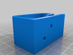
### Frames
This is system to create nice-looking frames, these are meant to bolt on to surfaces.
These are meant to remove similar code for creating mountings.
#### General modules
The `frames_curveToSlope()` is an internal module, creating a quarter of a stretched circle to the given dimensions.
The `minimalBridge()` module creates a bridge between two cylinders, with a curve to minimise plastic use, which exactly matches the two cylinders at either end.
Its full parameter list is very long:
`minimalBridge(minW, h= undef, h1 = undef, h2 = undef, d = undef, r = undef, d1 = undef, d2 = undef, r1 = undef, r2 = undef, sep = undef, l = undef, l1 = undef, l2 = undef, speed = 1, $fn = 500, hRoundfn = 100);`
These parameters are designed to mimic that of `cylinder()` in that only one of several different ways to specify each feature need be used,
it is recommended to use `h = 5` rather than using the ordering of the parameters.
The `minW` parameter specifies the narrowest width of the bridge. If this is smaller than either diameter, the module will simply `hull()` the two cylinders.
These are the different kinds of parameters:
##### Diameters
- `d` the simplest way, specifies the diameter of both cylinders.
- `r` also very simple, specifies the radius of both cylinders.
- `d1`, `d2` specifies the diameter of cylinder 1 and 2 respectively: must be used together
- `r1`, `r2` specifies the radius of cylinder 1 and 2 respectively: must be used together
##### Heights
- `h` the simplest way, specifies the height of both cylinders
- `h1`, `h2` specifies the heights of cylinder 1 and 2 respectively: must be used together
If the heights are different, some method of joining the cylinders can be used. The method used is specified by the speed parameter,
which specifies how performance intensive an operation should be used. Each value has different effects:
- 2 simply makes one taller than other, no joining performed, is the default.
- 1 hulls the two cylinders, while preserving bridge shape, looks alright, depending on circumstance, can look weird.
- 0 creates a rotational extrude of an inverted curve, very pretty, very performance intensive.
##### Separation/Location
There are different ways of controlling the location of the two cylinders (only in 2D space)
- `sep` This specifies the separation, cylinder 1 at `[0, 0]`, cylinder 2 at `[sep, 0]`
- `l` specifies location of cylinder 2, as a 2D vector, cylinder 1 at `[0, 0]`, cylinder 2 at `l`
- `l1`, `l2` specifies location of cylinder 1 and 2, as 2D vectors, cylinder 1 at `l1`, cylinder 2 at `l2`
##### Side numbers ($fn)
There are two values of $fn used. this is due to the different requirements of different parts of the shape.
The cylinders used to create the curve need comparatively high side count,
as they can be very large, but the shaping used at `speed = 0` needs comparitivly low $fn or the performance becomes unbearable,
this second value is what `hRoundfn` is for.
##### Example
minimalBridge(8, h1 = 5, h2 = 10, d1 = 20, d2 = 10, l1 = [20, 0], l2 = [0, 20], speed = 0, $fn = 500, hRoundfn = 100);
#### Frame modules
There are 7 different frame styles available, each of which tried to be consistent style,
so that the difference is more aesthetic that functional,
although some will be stronger, and some use less plastic.
- `frames_flatBase` this is never a complex part, and will rarely even do the expected job, but is the simplest thing with the specified footprint, more for demo and testing than actual use
- `frames_roundedBase` this does the simplest thing that works, building a tall base, with holes for bolts. It sometimes has some customisation, but rarely much
- `frames_hullBase` this does a simple `hull()` operation over the necessary parts, so is simple, but uses less plastic than `frames_roundedBase`, although can look weird with rounded corners
- `frames_pyramidBase` this does a more complex `hull()` with slightly angled corners, resulting in a simple shape, but less weird than simple hull
- `frames_sphericalBase` this creates rounded corners everywhere, generally working better as the top of a part, very performance intensive
- `frames_inverseCurve` this creates almost the exact opposite of `frames_sphericalBase` looking good leading up to a pillar, very performance intensive
- `frames_bridgeBase` uses the `minimalBridge()` module for everything, making it quite light on plastic, and looking more skeletal than the others, performance cost depends on `speed` variable
The general idea is to use the same style across a design, so that the parts look similar.
For each kind of base, there is a separate module, e.g. `frames_roundedBaseAngle`, however much like the core systems, there are selectors, and these are recommended,
it is also recommended to use the names of variables when assigning them for these modules, as there are a lot, and it can become confusing.
There are three ways of creating bases, for different kinds of base:
##### Four bolt
frames_base(baseType, boltSepX, boltSepY, baseT, boltType, boltSize, cornerD, h, topDimensions, corneringEffectLevel, circular, center, speed);
This creates a simple four bolt base, with bolt separations specified by `boltSepX` and `boltSepY` for the two dimensions of separation.
- `baseT` is the thickness of the underlying board, which parts are built onto.
- `boltType` and `boltSize` specify the bolts to be used at the corners of the base.
- `cornerD` specifies the size of the rounded corners, around the bolts.
- `h` specifies the maximum height, including the baseT, so above what it's screwed onto.
- `topDimensions` can either be a number (for a square or circle) or a vector (for a rectangle)
- `corneringEffectLevel` is a little arbitrary, it effects the amount of diagonal used for pyramid, the rounding factor for spherical and inverse, and the minW for bridge
- `circular` is a boolean, if true, the `topDimensions` vector's first value, or value is set to a simple number, is used as the diameter of a cylinder to act as the top surface.
- `center` is a boolean, if set to true, the base will be centred about the origin (although not height wise) otherwise, it will be centred about the first bolt hole.
- `speed` is used for the speed variable of the bridges in `frames_bridgeBase`
Example:
frames_base(frames_hullBase, boltSepX = 40, boltSepY = 30, baseT = 5, boltType = allenBolt, boltSize = M3, cornerD = 8, h = 10, topDimensions = [30, 15], corneringEffectLevel = 8, circular = true, center = false, speed = 1);
##### Two bolt
frames_base2(baseType, boltSep, baseWidth, baseT, boltType, boltSize, h, topType, topW, topL, center, speed);
Some of the parameters are the same, but the differences are:
- `boltSep` defines the separation of the bolts, there is only one axis for this.
- `baseWidth` defines the width of the part, similar to `cornerD`, but defines some of the properties of the top part (how wide it is).
- `topW` defines the size of the top, the exposed connection point.
- `topL` only used for some values of `topType`, other value.
`topType` defines the kind of top the part should have, it can have any one of five values:
- `framesTop_none` this is the default if any invalid value is given, acts like `frames_flatBase`
- `framesTop_square` creates a rectangular top section, of size `[topW, baseWidth]`
- `framesTop_cylindrical` creates a cylindrical top section, of diameter `topW`
- `framesTop_crossCylinder1` creates a cylindrical top section, going across the short width of the piece, of diameter `topW`
- `framesTop_crossCylinder2` creates a cylindrical top section, going across the length of the piece, of diameter `topW`, and length `topL`
Example:
frames_base2(frames_hullBase, boltSep = 40, baseWidth = 8, baseT = 5, boltType = allenBolt, boltSize = M3, h = 20, topW = 10, topL = 10, corneringEffectLevel = 5, topType = framesTop_square, circular = false, center = false, speed = 0);
##### Angle
frames_baseAngle(baseType, plateW, plateH, baseHoleSep, baseT, plateT, boltType, boltSize, cornerD, strutT, center = false, speed = 2)
Again, some of the parameters are the same, but the differences are:
- `plateW` the usable width of the vertical plate, with no obstructions.
- `plateH` the usable height of the vertical plate, with no obstructions.
- `plateT` the thickness of the plate.
- `strutT` the thickness of any struts used for support
Since the distance between the bolts is not consistent across the styles, there are functions to get it:
getBaseAngleFrontXBoltSep(baseType, plateW, strutT, cornerD)
getBaseAngleRearXBoltSep(baseType, plateW, strutT, cornerD)
Example:
frames_baseAngle(frames_hullBase, plateW = 20, plateH = 20, baseHoleSep = 20, baseT = 5, plateT = 5, boltSize = allenBolt, boltSize = M3, cornerD = 8, strutT = 5, center = false, speed = 2);
## Functions and Modules provided
Standard meanings of variable names:
- `size`: e.g. `M2`
- `length`: the length of a bolt below the head, e.g. 20 (except for countersunk, where it measures from top of head)
- `ERR`: amount added to sides of head and shaft to compensate for overprint, make it negative to compensate for under-print
- `holeDepth`: The depth of the hole leading up to the bottom of the bolt head (except for countersunk, where it measures from top of head)
hollow: boolean, whether to render part itself rather than create the hole for it, not really that useful
- `VertERR`: the versicle error on nuts, used to mount nuts horisontally and deal with the overhand drooping slightly
- `distFromEdge`: the distance the nut is from the edge of the material, to define the size of the hole cut
- `nutType`: the type of nut, as defined within the nut selector
- `washerType`: the type of washer, as defined within the washer selector
- `boltType`: the type of bolt, as defined within the bolt selector
- `override`: creates a object even if not recommended.
- `silent`: makes the system not complain if small problems are detected (useful if you want to get on with it anyway, and not fill up the console, counter to repeated "WARNING: Button bolts won't look good inset")
### Functions
- `M(size, value_required)` The basic indexing function, used to retrieve values from the database.
- `getRodD(size)` A higher level way of saying `M(size, boltD)` implemented to allow better compatability with ScrewsUniversal
- `isValueInScrewsDatabase(a, b)`
- `isBoltInScrewsMetric(boltType, size)`
- `getHeadDiameter(boltType, size)`
- `getHeadHeight(boltType, size)`
- `isWasherInScrewsMetric(washerType, size)`
- `getWasherDiam(washerType, size)`
- `getWasherT(washerType, size)`
- `isNutInScrewsMetric(nutType, size)`
- `getNutH(nutType, size)`
- `getNutPeakD(nutType, size)`
- `getNutFlatD(nutType, size)`
### Modules
- `Rod(size, length, ERR, hollow);`
#### Bolts:
- `AllenBolt(size, length, ERR,hollow);`
- `HexHeadBolt(size, length, ERR,hollow);`
- `HexHeadFlangeBolt(size, length, ERR, hollow);`
- `AllenButtonBolt(size, length, ERR, hollow);`
- `AllenCountersunkBolt(size, length, ERR, hollow);`
#### Bolt holes:
- `AllenBoltHole(size, length, holeDepth, ERR);`
- `HexHeadBoltHole(size, length, holeDepth, ERR);`
- `HexHeadBoltHoleAllowingSpin(size, length, holeDepth, ERR);`
- `HexHeadFlangeBoltHole(size, length, holeDepth, ERR);`
- `AllenButtonBoltHole(size, length, holeDepth, ERR);`
- `AllenCountersunkBoltHole(size, length, holeDepth, ERR);`
#### Washers:
- `FormAWasher(size, ERR, hollow, VertERR);`
- `FormBWasher(size, ERR, hollow, VertERR);`
- `FormCWasher(size, ERR, hollow, VertERR);`
- `FormDWasher(size, ERR, hollow, VertERR);`
- `FormEWasher(size, ERR, hollow, VertERR);`
- `FormFWasher(size, ERR, hollow, VertERR);`
- `FormGWasher(size, ERR, hollow, VertERR);`
#### Nuts:
- `ThinSquareNut(size, ERR, hollow, VertERR);`
- `SquareNut(size, ERR, hollow, VertERR);`
- `StuddingConnector(size, ERR, hollow, VertERR);`
- `FullNut(size, ERR, hollow, VertERR);`
- `NylockNut(size, ERR, hollow, VertERR);`
- `DomeNut(size, ERR, hollow, VertERR);`
- `WingNutLocked(size, ERR, hollow, VertERR);`
- `WingNutRotatable(size, ERR, hollow, VertERR);`
#### Nut holes:
- `FullNutHole(size, distFromEdge, ERR, VertERR);`
- `DomeNutHole(size, distFromEdge, ERR, VertERR);`
- `NylockNutHole(size, distFromEdge, ERR, VertERR);`
- `ThinSquareNutHole(size, distFromEdge, ERR, VertERR);`
- `SquareNutHole(size, distFromEdge, ERR, VertERR);`
- `StuddingConnectorHole(size, distFromEdge, ERR, VertERR);`
- `WingNutLockedHole(size, distFromEdge, ERR, VertERR);`
### Selectors:
#### Bolts:
For these, the surface is at z = 0
- `BoltOnSurface(boltType, size, length, ERR, hollow, silent);`
creates the bolt on the surface
- `BoltFlushWithSurface(boltType, size, length, ERR, hollow, override, silent);`
insets bolts into surface
- `BoltNormalWithSurface(boltType, size, length, ERR, hollow, silent);`
Does the most common action, whatever makes most sense
#### Bolt holes:
- `BoltInHoleFromTop(boltType, size, length, holeDepth, ERR, hollow, silent);`
Measures from the top of the bolt head, making a hole above for the bolt to enter.
- `BoltInHoleFromBottom(boltType, size, length, holeDepth, ERR, hollow, silent);`
Measures from bottom of the bolt head, making a hole above for the bolt to enter.
- `BoltInHoleFromNormal(boltType, size, length, holeDepth, ERR, hollow, silent);`
Measures wherever is most applicable on that type of bolt, making a hole above for the bolt to enter.
#### Washers and Nuts:
- `Washer(form, size, ERR, hollow, VertERR);`
- `Nut(nutType, size, ERR, hollow, VertERR);`
- `NutHole(nutType, size, depth, ERR, VertERR);`
## Internal Structure
The ScrewsMetric.scad file, the one which is included, includes all the internal files,
in a good order to ensure that the echo statements arrive in a good order, and aren't repeated.
There are several components to ScrewsMetric as represented by the files found in Internal:
- ScrewsMetric-core.scad
- ScrewsMetric-core-modules.scad
- ScrewsMetric-core-BoltSelector.scad
- ScrewsMetric-core-NutSelector.scad
- ScrewsMetric-core-Washers.scad
Other files are assistance only and have little code.
The files break into two categories: the `core` files, and the others.
All module and function names within the `core` files begin with `M_`.
Do not call these directly, use the simple name, the `M_` is to provide compatibility with ScrewsUniversal,
so that the underlying modules can be preserved, only needing new modules for the top level module,
which can then call the relevant underlying module in ScrewsMetric, or ScrewsUNC as appropriate.
The other files are designed to act as interfaces onto the core files.
The break down is as follows:
- ScrewsMetric-core.scad is the central database, nothing but piles of variables, a huge array and an access function.
- ScrewsMetric-core-modules.scad is a set of modules, each creating a single object, such as a full nut or a hex bolt.
- ScrewsMetric-core-BoltSelector.scad is a system for choosing bolts using a variable, meaning a countersunk bolt could be quickly changed for a button bolt.
- ScrewsMetric-core-NutSelector.scad is a system for choosing nuts based on a variable, meaning that a hex nut could be quickly changed for a square nut.
- ScrewsMetric-core-Washers.scad is a separate database, holding the dimensions for different washers, as well as providing an access function, and a module to create a washer.
- ScrewsMetric-BoltSelector.scad is an interface onto core-BoltSelector, merely giving an echo statement and naming modules.
- ScrewsMetric-NutSelector.scad is an interface onto core-NutSelector, merely giving an echo statement and naming modules.
- ScrewsMetric-Washers.scad is an interface onto core-WasherSelector, merely giving an echo statement and naming modules.
- ScrewsMetric-Base.scad is an interface onto core, merely giving an echo statement.
- ScrewsMetric-Modules.scad is an interface onto core-modules, merely giving an echo statement and naming modules.
All Optional modules avoid addressing the structure in any way, calling modules which they have not loaded, but openscad doesn't mind as long as they are present at runtime.
They can address sizes etc. through the `ScrewsMetric-sizeDeclaration` file, which merely acts like a .h file in c, only declaring the necessary global variables.
These sizes can be used, for example, to allow the specification of a size of bolt, e.g. for steppers.
All the lookups are done though indexing, so `M8` is really equal to 6
Using the numeric value of the index HAS NO MEANING WHATSOEVER and using indexes instead of the names is also not recommended, it just makes things harder to read.
Doing any numerical operation on any of the indexes will also lead to a nonsensical result, as the indexes are not necessarily in size order:
`echo(M2_5 > M8);`
comes out true
The underlying array is called `M`
so `M[boltD][M2]` gives the same result as `M(M2, boltD)`,
however if a non-existent value is indexed, `undef` is returned, resulting in many hard to find bugs.
There is also no guarantee that the underlying array will not change its structure,
for example it may invert and become `M[M2][boltD]` without any warning,
the structure may also change, so there is no array, so using it is asking for problems in a version update.
If you want to check whether a value exists, use `isValueInScrewsDatabase(a, b)`
giving it the same values as you would the `M()` function.
This will not fail if the value does not exist, and will work if converted to ScrewsUniversal, with either metric or imperial.
Each value is assigned to a variable before being entered into the array, these variables follow the pattern:
`M2_nutPeakD`
which is returned by
`M(M2, nutPeakD)`
Do not use these values directly, it is no more compact than indexing them,
and no faster as almost all performance losses in OpenScad are in the rendering.
`hollow` is used as an argument to many modules to make them go into display mode, the results are not accurate, and are just there to look pretty.
`AllenBoltHole()` is a module which creates a channel leading to the head, to allow fully embedded bolts
`FullNutHole()` is a module which creates a channel leading to a nut, to allow it to be side inserted.
The array for the washer system is accessed through `WasherDimensions()`, e.g. `WasherDimensions(M8, washerFormA, washerT)`,
however higher level functions should be used, `Washer(WasherDimensions, M8)` providing the general module,
the functions `getWasherT(form, size)` and `getWasherOuterD(form, size)` providing the information.
The modules `FormAWasher(size)` through to `FormGWasher(size)` call the Washer module, so are actually more indirect.
This is because the layout of the array makes it easy to switch between values, and all washers are fundamentally the same shape.
Direct link to the original creator's page
More from mbef


Similar Models


Model Specifications
Frequently Asked Questions
How do I download ScrewsMetric?
Click the "View on thingiverse" button above to visit the original model page on thingiverse. You can download the STL file directly from the creator's page for free.
What 3D printer can I use for this model?
This STL file is compatible with most FDM 3D printers (Creality Ender 3, Prusa MK3S+, Bambu Lab, etc.) and resin printers (Elegoo, Anycubic). Check the original page for recommended print settings and materials.
Is this 3D model free to download?
Yes, this model is available as a free download on thingiverse. Some creators accept tips or donations.
Can I modify this STL file?
Most STL files can be modified using free software like Blender, TinkerCAD, or Meshmixer. Check the license on the original thingiverse page to see if modifications are permitted by the creator.