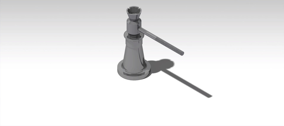
Screw Jack
grabcad
Designing a Screw Jack Using CATIA V5 To design a screw jack utilizing CATIA V5, start by launching the software and accessing the Part Design workbench. From there, create a new part file by clicking on "File" followed by "New." This will prompt you to select a template for your project; choose the "Part Design" option. Next, establish a reference point for your design. In this case, we'll be working with a 2D layout, so create a sketch by clicking on the "Sketch" tool in the toolbar. Set the units of measurement and select a plane to work on. Draw a rectangle representing the base of the screw jack. To add a profile to the part, use the "Revolve" feature. Select the sketch you created earlier and choose the "Revolve" option from the toolbar. This will generate a 3D model of the screw jack's body. Add material properties by clicking on the "Material" button in the Properties panel. Now, let's move on to designing the screw mechanism. Create another new part file for the screw component. Draw a cylinder representing the screw shaft and add threads using the "Helix" feature. Ensure the helical angle is set correctly to achieve proper engagement with the nut. Assemble the screw jack by creating a mate relationship between the two parts. Use the "Mate" tool to link the screw shaft to the base of the assembly. Finally, save your design and export it as an IGES file for further analysis or manufacturing.
With this file you will be able to print Screw Jack with your 3D printer. Click on the button and save the file on your computer to work, edit or customize your design. You can also find more 3D designs for printers on Screw Jack.