SAE/Inch Parametric Gear Collection
prusaprinters
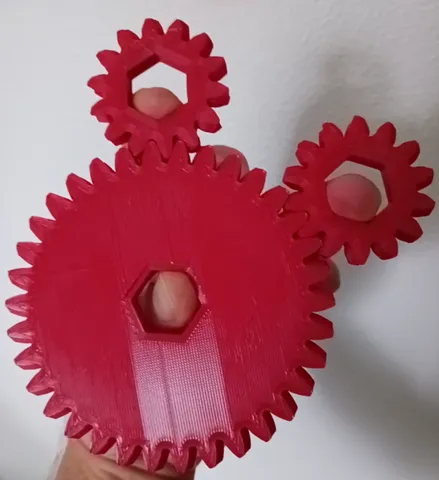
SI/Metric version coming soon! (Ideally)This is my (almost) fully parametrically driven gear file. The module, tooth count, tooth size, profile shift, and reference pitch diameter are all equation driven in the Solidworks file attached. Additionally, the gear is separated into 4 planes where the angle of each tooth can be modified relative to the patterned teeth in the other planes, allowing for spur, swept, sharp & blunted herringbone, or even zig-zag mating surfaces between teeth. These planes can have their offsets changed to determine the thickness of the gears with respect to each part of the tooth profile as well.For those without access to Solidworks, a series of blunted Herringhone and spur gear stls are included. The module, tooth count, and tooth point profile are as listed in the file name. A profile shift prevents the gear teeth from bottoming out, so achieving proper spacing should be as simple as just shoving the gears together. There are tools available such as the Fusion360 gear maker that probably could have been easier than this with comparable functionality, but here we are anyway. All stl gears included feature: P1 = module of .1 in or 2.794 mm (written as p1 in file names to prevent misreadings)Hexagonal center sized to fit a ½” or M12 hex nut (3/4” or 19mm Hex width between flats)Pressure Angle = 20 degProfile shift coefficient = .25 (Keep tooth tip width >= .2*module if changing parameters other than this) Tooth Depth = .23837” / 6.054598 mm Thickness of .4” / 10.16 mm Measurements of included stls are as follows. I attempted to get close to whole millimeters or half inch fractions for each reference diameter.Teeth count -> External Rad ;; Reference Pitch Diameter (effective diameter when mated with another gear)15 -> .8625” / 21.9075 mm ;; 1.5” / 38.1 mm17 -> .9625” / 24.4475 mm ;; 1.7” / 43.18 mm20 -> 1.1125” / 28.2575 mm ;; 2.0” / 50.8 mm25 -> 1.3625” / 34.6075mm ;; 2.5” / 63.5 mm30 -> 1.6125” / 40.9575 mm ;; 3.0” / 76.2 mm35 -> 1.8625” / 47.3075 mm ;; 3.5” / 88.9 mm40 -> 2.1125” / 53.6575 mm ;; 4.0” / 101.6 mm45 -> 2.3625” / 60.0075 mm ;; 4.5” / 114.3 mm50 -> 2.6125“ / 66.3575 mm ;; 5.0” / 127.0 mm55 -> 2.8625“ / 72.7075 mm ;; 5.5” / 139.7 mm60 -> 3.1125“ / 79.0575 mm ;; 6.0” / 152.4 mmInside the File: Changing Parameters:If you are able to open the Solidworks file, you will be able to change nearly all parameters of the gear from the equation screen. For those wondering about Solidworks version compatibility, the current file is exported from Solidworks Premium 2022. This means it should be compatible with both business and personal/maker licenses that can open 2022 edition (or later) files. Tooth Count (Z_Teeth): The typical involute gear tooth count limits of z = 17 as the general minimum or z = 14 minimum with a profile shift still apply. I have a profile shift included by default that should allow for Z_Teeth counts between 15 and 17 at a module of .1”, but depending upon your module change you may need to edit the profile shift further to accommodate your desired tooth count/diameter. Errors with Z_Teeth count changes (Likely calculation time): When changing tooth count (with a usable profile shift in place), you will potentially receive an error that will resolve itself upon exiting the equation screen. I believe this is due to slow calculation times on the old/weak computer I’m currently running Solidworks on, but if it’s not processing time that is causing the error please be aware that this is typically a false flag that will resolve itself with a ctrl+G if one of the loft ends doesn’t resolve properly after exiting the equation screen (again, as long as your current profile shift is appropriate for the tooth count). Thus far, I have not had any problems with mating/printing of the gears but I think that the error is still important to note for other users.Module: Module can be changed to affect tooth size for your gear. The minimum module that I’ve reached using this file is .09” / 2.286 mm. Please keep in mind that the profile shift will likely need to be changed if you do choose to modify the module. In the current state of the Solidworks file, I personally recommend keeping the module to values greater than or equal to .11” / 2.794mm.Please keep in mind that gears must share the same module to mate properly.Profile Shift: Included by default is a profile shift coefficient of .25, originally calculated to allow a Z_Teeth count of 14 with a module of .11in. Profile shifting will affect the shape of your teeth, either narrowing or widening the tips of each tooth. Profile shifting allows you to shape the teeth to avoid bottoming out for low tooth counts or can allow you to make the teeth more robust for large gears with many teeth.Despite its effect on the shape of the gear teeth, a pair of gears do not have to share the same profile shift gears to mate properly.Mating Surfaces:As seen with the 3 gear types included as stls, you can alter 3 equations to change the mating interfaces of your gears. These equations are labelled as “HelicalShiftInside”, “HelicalShiftInside_Far”, &“HelicalShiftOutside_Far”. These equations allow you to shift the angle between each flat end of a tooth loft and that of the profile on the other side of the same loft. Identical values will result in a spur gear, continuously increasing angles will result in a swept profile, etc.. Do not change the equation “HelicalShiftOutside”, as this affects the initial tooth curvature all other tooth sketches are derived from. Pressure Angle: This is the angle at which the slope of a pair of gear teeth meet. Generally this will either be 20 degrees (the modern standard) or 14.5 degrees (the old standard). Unless you are intending to do replacement work for old equipment, I do not advise changing this from 20 degrees. If you are replacing worn out parts on old equipment, you probably should get metal replacements rather than these.
With this file you will be able to print SAE/Inch Parametric Gear Collection with your 3D printer. Click on the button and save the file on your computer to work, edit or customize your design. You can also find more 3D designs for printers on SAE/Inch Parametric Gear Collection.