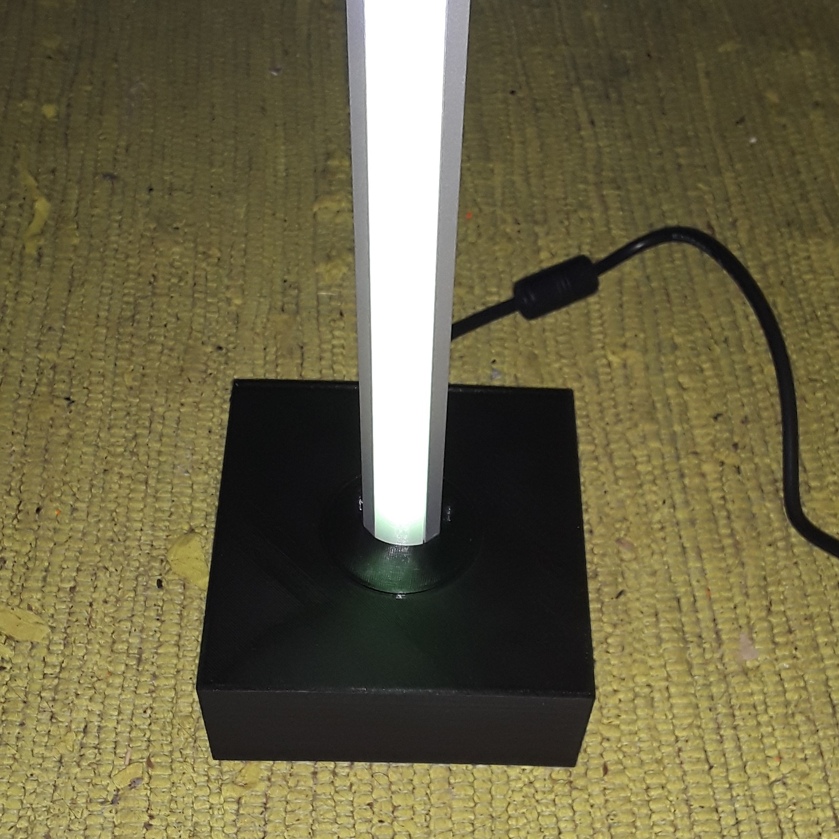
Rotatable led bar lamp
prusaprinters
<p>This is a generic (and slightly overengineered) case to build a "Stick" Light with a LedStrip and a controller. It is build to match the <a href="https://github.com/srg74/WLED-wemos-shield">wled Board from Serg74</a>, but you can use other controllers, too. </p><p><strong>The case has the following features:</strong></p><ul><li>The "Stick" is rotatable 355° without the need to rotate the case itself.</li><li>The rotation has snap points to reach exact angles.</li><li>The rotation has a stop to avoid more than one turn (to safe the wire from twisting more than necessary).</li><li>Case walls are hollow to add some weight (nuts) for standing safety, if you want.</li><li>There is space and a holder for a <a href="https://www.amazon.de/2-5V-5-5V-Capacitive-Self-Lock-Arduino-Microwave/dp/B07FLV9J7R/ref=asc_df_B07FLV9J7R/?tag=googshopde-21&linkCode=df0&hvadid=311060251637&hvpos=&hvnetw=g&hvrand=15877384305277460620&hvpone=&hvptwo=&hvqmt=&hvdev=c&hvdvcmdl=&hvlocint=&hvlocphy=9042083&hvtargid=pla-633210293891&psc=1&th=1&psc=1&tag=&ref=&adgrpid=64713226027&hvpone=&hvptwo=&hvadid=311060251637&hvpos=&hvnetw=g&hvrand=15877384305277460620&hvqmt=&hvdev=c&hvdvcmdl=&hvlocint=&hvlocphy=9042083&hvtargid=pla-633210293891">TTP332 touch sensor pcb</a> on top of the case (invisible from outside).</li><li>There is a small hole at the upper front side to reach the pcb's onboard switch (some kind of pin needed)</li><li>Modular design, can easily be adopted to your needs.</li><li>The case has three cutouts at the backside and matching push-in pieces to use with different sockets/plugs according to your setup and wishes. (Max. setup I tought about is powerIn, lineIn and chaining)</li></ul><p><br><strong>Included are the following push-in pieces:</strong></p><ol><li>For powersocket 5,5mm (2,1mm Pin) external screwed</li><li>For powersocket 5,5mm (2,1mm Pin) internal screwed</li><li>For LineIn (jack) socket 3,5mm external screwed</li><li>For LineIn (jack) socket 3,5mm internal screwed</li><li>For Wire pass thru (max 2 x 1,5²mm) with strain relief</li><li>A blank one to close unneeded space, or for your special requirements</li></ol><figure class="image"><img src="https://media.printables.com/media/prints/301348/rich_content/49da9576-52dd-499c-8ff9-25b8697c4822/20221024_132442.jpg#%7B%22uuid%22%3A%22791f74f8-6e42-4007-bf80-14a09f6fafff%22%2C%22w%22%3A2942%2C%22h%22%3A1482%7D"></figure><p>Everything can be printed without supports. You can use PLA for the case, but I suggest PETG for the rotating disc and its fastening plate. PETG allows a smoother movement.</p><p><strong>What you need:</strong></p><ul><li>19 screws M3 x 6mm</li><li>2 "Spax" screws 3,5 x 30mm (or longer)</li><li>1 "Spax" screw 5,0 x 50mm (or longer)</li><li>1 Led alu profile in triangle shape, side length 18mm (see image) </li></ul><figure class="image image-style-align-center image_resized" style="width:35.16%;"><img src="https://media.printables.com/media/prints/301348/rich_content/cd5dae7a-46be-4ab9-a07c-a72fc3313642/2022-10-15-14_35_23-5xled-profil-aluprofil-alu-schiene-leiste-profile-fur-led-streifen-eloxiert-1m.png#%7B%22uuid%22%3A%220becf4ff-45e4-41e1-98c7-82bef58eec52%22%2C%22w%22%3A544%2C%22h%22%3A434%7D"></figure><ul><li>1 M4*10mm nylon screw, if wire pass thru piece is used, (for strain relief)</li></ul><p><strong>Assembly:</strong></p><p>1. Screw the two disc halves (#1 + #2) together (3x M3x6mm) </p><figure class="image image-style-align-center image_resized" style="width:50%;"><img src="https://media.printables.com/media/prints/301348/rich_content/efbd4cdc-4a69-45e7-909d-70f9d4b8149b/20221024_125232.jpg#%7B%22uuid%22%3A%22b95aa28f-3d18-4408-95fd-c8169a485eb0%22%2C%22w%22%3A2938%2C%22h%22%3A1526%7D"></figure><p><br>2. If your led strip has an connector, thread the strip through the disc! (There is not enough space to fiddle the connector through, so if you have already your strip glued to the profile, you have to cut off the connector and wire directly).<br>3. Now glue the led strip to the alu triangle profile and screw the disc to it (3 "Spax" screws) using the three triangle shaped holes. </p><figure class="image image-style-align-center image_resized" style="width:50%;"><img src="https://media.printables.com/media/prints/301348/rich_content/13a878be-50e1-4203-8316-28fd0256c9dc/20221024_125410.jpg#%7B%22uuid%22%3A%22da086d95-6831-4e35-9cf1-e53424478939%22%2C%22w%22%3A2963%2C%22h%22%3A1528%7D"></figure><figure class="image image-style-align-center image_resized" style="width:50%;"><img src="https://media.printables.com/media/prints/301348/rich_content/63809baa-9cab-4b28-94ac-7c7ad05b8ce2/20221024_130047.jpg#%7B%22uuid%22%3A%225dd16f7c-ef03-4c59-b3ad-91109646d7ad%22%2C%22w%22%3A2183%2C%22h%22%3A1699%7D"></figure><p><br>4. Insert the profile/disc item from inside through the hole in the base (#5). </p><figure class="image image-style-align-center image_resized" style="width:50%;"><img src="https://media.printables.com/media/prints/301348/rich_content/fea0f813-26bb-4666-8b49-e342ea91a864/20221024_130452.jpg#%7B%22uuid%22%3A%2206bab398-8045-47cd-881a-260ef9b8599b%22%2C%22w%22%3A2731%2C%22h%22%3A1836%7D"></figure><p><br>5. Bring the touch sensor in place (if used), it will be fastened with the next step. </p><figure class="image image-style-align-center image_resized" style="width:50%;"><img src="https://media.printables.com/media/prints/301348/rich_content/77d22759-1c17-4ea5-af39-3f260904812a/20221024_130350.jpg#%7B%22uuid%22%3A%22eac551a1-5469-41e1-b526-da509f35a2c7%22%2C%22w%22%3A1961%2C%22h%22%3A1836%7D"></figure><p><br>6. Mount the fastening plate (#6) over disc and touch sensor with 6 screws, let one side free. (6x M3x6mm). </p><figure class="image image-style-align-center image_resized" style="width:50%;"><img src="https://media.printables.com/media/prints/301348/rich_content/0a95fe38-ee26-48c9-b02e-2b81156fbf1f/20221024_131009.jpg#%7B%22uuid%22%3A%22e46e9cf4-3fc8-4e9d-9993-75e3b970c843%22%2C%22w%22%3A1618%2C%22h%22%3A1593%7D"></figure><p><br>7. Place the rotation stopper (#4) over the free side holes and mount it with another two screws (2x M3x6mm). </p><figure class="image image-style-align-center image_resized" style="width:50%;"><img src="https://media.printables.com/media/prints/301348/rich_content/a56047ec-b23e-4e46-b0bb-a1b1640e1eea/20221024_131231.jpg#%7B%22uuid%22%3A%2231ad05b7-3a82-49b3-b0f4-f151ad8de1aa%22%2C%22w%22%3A1416%2C%22h%22%3A1553%7D"></figure><p><br>8. Check whether rotation works as it should.<br>9. Mount the pcb to the base plate (#6) (4 x M3*6mm). </p><figure class="image image-style-align-center image_resized" style="width:50%;"><img src="https://media.printables.com/media/prints/301348/rich_content/cbe3405b-5c46-4f0b-8576-668d252e8264/20221024_131907.jpg#%7B%22uuid%22%3A%22046601c3-98ff-4d34-ad61-8cca517f48f8%22%2C%22w%22%3A2062%2C%22h%22%3A1640%7D"></figure><p><br>10. Prepare the plugin pieces (#7) according your plugs/jacks and connect them to your pcb.<br>11. Slide the plugin pieces (#7) into the base (#5) .<br>12. If you want, fill the hollow walls with nuts or whatever you prefer.<br>13. Mount the baseplate (#6) to the case (#5) (4 x M3*6mm). </p><figure class="image"><img src="https://media.printables.com/media/prints/301348/rich_content/6c2f487c-31f1-4920-95a2-92b52eb85af2/20221024_164633.jpg#%7B%22uuid%22%3A%22e76888dc-a328-4fe6-bfe8-5d9e5ecd9c64%22%2C%22w%22%3A1716%2C%22h%22%3A1716%7D"></figure><p><br> </p>
With this file you will be able to print Rotatable led bar lamp with your 3D printer. Click on the button and save the file on your computer to work, edit or customize your design. You can also find more 3D designs for printers on Rotatable led bar lamp.
