Robotic arm "Cpt. Hook"
thingiverse
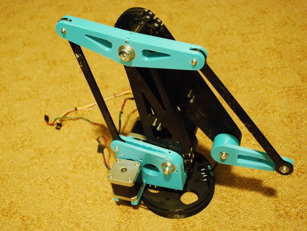
A Cutting-Edge Design: High Precision 3D Robotic Arm Powered by NEMA 17 Stepper Motors A cutting-edge attempt to create a high precision 3D robotic arm driven by reliable NEMA 17 stepper motors. At this stage, it's merely stored here for the moment; don't expect an in-depth description or instructions just yet, as I'm working on a functional prototype. Feel free to download it, but please note that I won't be able to offer consistent support until the development is complete. The design's name was inspired by the infamous pirate's missing limb, aiming for a compact attachment to a desk. The planned manipulation area is roughly 200mm deep, 200mm high, and features 270° sidewise motion. Precision Motors: Motors with 400 steps per turn will be utilized alongside 32 microstepping drivers. To eliminate backlash while increasing precision, T2.5 timing belts with a 1:5 reduction ratio will power the arms. The turning system has a 1:10 reduction rate. Achievable Precision: If motors maintain their position on microsteps, the movement's precision would approach 10μm within the designated area. Complex Movement Requirements: The calculation of three angles exceeds simple orthogonal motion requirements. Consequently, I anticipate using electronics more powerful than Arduino Mega but am still searching for suitable alternatives. Collaboration Welcome: Any help, support, or insightful comments are greatly appreciated. Change Log: * 2015-01-13 Version 1.0 Designed. Version 1.0 was designed but turned out to be overly massive and consumed too much time and filament. Slic3r struggled to prepare supports as they were too light. Pulleys did not fit precisely onto the T2.5 belt. * 2015-01-29 Version 1.1 Prepared. A lighter design version, 1.1, was prepared, addressing issues with printable supports. Corrections were made for M3 and M4 screws, and holes in the drawbar system. The part where belts were attached underwent redesign. * 2015-02-10 Assembly Version 1.2 Uploaded. Changes necessary for easier assembly of the robot were uploaded in version 1.2, along with typical metric screw lengths added to the bill of quantities (BoQ). * 2015-03-16 Mechanical Operations The robotic arm is operational mechanically, but it's a mix of various versions and prints from two non-calibrated 3D printers. Images were included in the gallery; upward movement was somewhat limited due to a faulty drawbar system. * 2015-05-15 Test Movement Test movement showed that motors ran hot since they needed permanent holding, so a fan holder model was uploaded. A friend developed an excellent application for simulating arm movement and determining deviations from the desired position with a precision of 0.025mm in X, 0.021mm in Y, and 0.042mm in Z axes. * 2015-05-17 Customized Marlin Firmware Dan made a customized fork of Marlin to power the arm, initially tested on Atmega2560, which provided some bumpy results due to imprecise shape measurements. A calibration desk was designed for obtaining correct figures. * 2015-05-18 New Tool Holder Design A new tool holder and swing design were created that can accommodate a Jhead or E3D Bowden extruder with no guarantee of its success but it is definitely an improvement over the original 3mm hole design. Some slight changes were made in arms one and two. * 2015-06-20 Caution on Printing Materials Important note to always check if your printed items are not left unattended in a hot car as can be seen in the picture gallery for clear proof. \nInstructions The project is designed to accommodate 0.15mm overflow to either side when printed, hence it is recommended to print all parts on common PCB heatbed 200x200mm with this tolerance already considered. Note that embedding supports are necessary for some of these prints as bridge support walls which are only 0.25mm thick will print out smoothly with no problem using even 0.5 wide nozzle, also the part's bridges' thicknesses have been set at this optimal amount which makes them very easy to remove. Some initial tests were performed using PLA at home with an ABS model made on a common semi professional 3D printer; however some errors were noticed with timing belts when trying pulleys with wider teeth - round and shallow but generally it did okay otherwise. A bill of quantity sheet has been provided as excel document BoQ.xls. Since some measurements have still to be determined so measure all lengths carefully before proceeding
With this file you will be able to print Robotic arm "Cpt. Hook" with your 3D printer. Click on the button and save the file on your computer to work, edit or customize your design. You can also find more 3D designs for printers on Robotic arm "Cpt. Hook".