Revision III Tricopter
prusaprinters
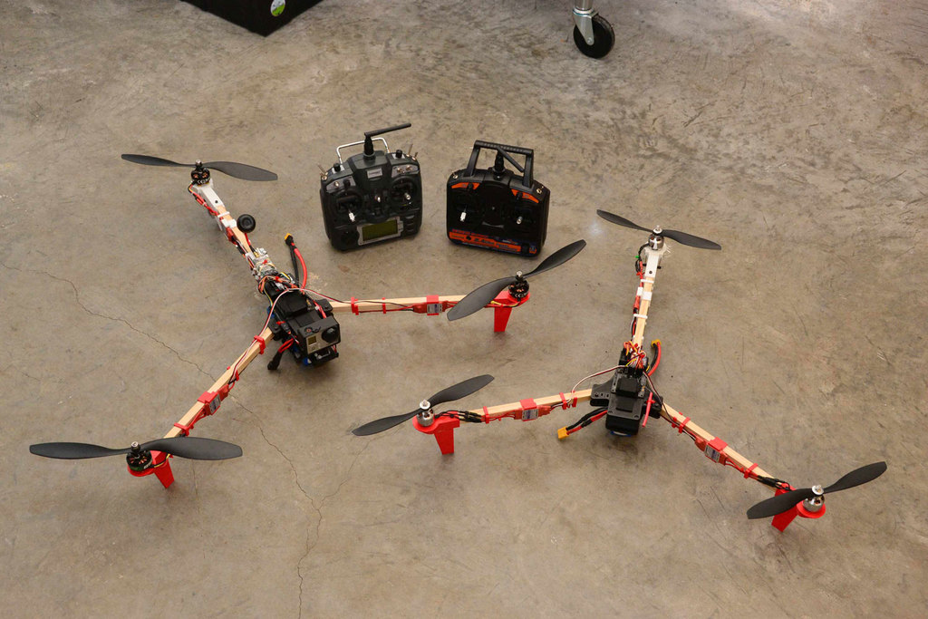
<p>It's finally here!</p> <p>See instructions for details. Many parts are optional.</p> <p>Early test flight: <a href="http://youtu.be/IVNpG9oJvUg">http://youtu.be/IVNpG9oJvUg</a></p> <p>I modified Thingiverse user ennui2342's tricopter body, based off of David Windestal RCExplorer tricopter, to support the stronger, more common (in the US) 1/2inch wood dowels. Other modifications were made as well. I also loosely based my landing gear/motor mounts off of jphillips' designs. The vibration dampening bottom plates among other features are unique to this tricopter.</p> <p><strong>Update</strong>: I added "optional-plate_larger_motor_mounts_kit.stl" which supports larger (unnecessary) motors that use an 18.9/25mm through 25/25mm mounting hole spacing.</p> <p><strong>Update 2</strong>: I don't know if there is a demand for them, but I designed extra-long versions of the landing gear/motor-mounts (22mm taller). They are published as "optional-plate_larger-longer_motor_mounts_kit.stl" and "optional-plate_standard-longer_motor_mounts_kit.stl"</p> <p><strong>Update 3</strong>: I added a bonus IMU shield for exposed IMUs and flight control PCBs (imu-shield.stl). View later picture to see how it is mounted. You will need some VHB tape and soft foam as well. This not only protects the IMU, but also mitigates undesired noise from exposed digital barometers. (not included in the "full plate")</p> <p><strong>Update 4</strong>: Fixed and reuploaded "optional-plate_3_esc_clips.stl". Original file was malformed and causing errors in some slicers.</p> <p><strong>Update 5</strong>: Added "upgraded-optional-gopro_fpv_plate.stl" as an upgrade to the old multipurpose FPV plate + GoPro shoe. This package is now more rigid and strictly designed to be pared with the (unchanged) GoPro shoe. It should mitigate any resonant vibration issues caused by flexing of the plastic. Simply mate the top of this plate with the top of the battery plate using glue or tape and re-thread your zip-ties. The slanted face should be face down. (not included in the "full plate")</p> <p><strong>Update 6</strong>: Added an larger optional countersink plate. Perfect for larger flight controllers, GPS units, and other bits of extra hardware. Tip: use wide strips of Velcro under this plate for easy access to the screws underneath.</p> <p><strong>Quick specs:</strong></p> <p>Here is what I currently fly with this frame. MANY other hardware choices will also work just as well or perhaps a bit better.</p> <p>-Turnigy 5000mAh 3S 40C LiPo</p> <p>-Multistar 3525-850Kv Outrunner</p> <p>-Turnigy Plush 25A ESC</p> <p>-APC 13x5.5MR(P) props</p> <p>-BMS-385DMAX Digtal Servo</p> <p>For a full, more detailed write-up, visit: <a href="http://goo.gl/K1WBVQ">http://goo.gl/K1WBVQ</a></p> <h3>Print Settings</h3> <p><strong>Rafts:</strong></p> <p>Doesn't Matter</p> <p><strong>Supports:</strong></p> <p>Yes</p> <p><strong>Infill:</strong></p> <p>*See notes.</p> <p><strong>Notes:</strong></p> <p>Infill for the motor mounts should be between 60% to 100%. and should be printed with a high temperature tolerant plastic, such as ABS. (PLA will work, but will also fail spectacularly if your motors get too warm.)</p> <p>The infill for the main frame pieces can usually be anything greater than 25-35%.</p> <h3>Instructions</h3> <p><strong>For more details and pictures, visit the link at the bottom of this section.</strong></p> <p>Print quantities are stated in file names (likely just one of each) and optional extras. The optional cable and ESC clips are highly encouraged.</p> <p>Some things you will most certainly need for the frame:</p> <ul> <li>3M VHB tape</li> <li>5mm wide zip-ties</li> <li>13x 25mm M3 socket cap screws</li> <li>13x M3 Nylock nuts</li> <li>1x 35mm M4 socket cap screw</li> <li>1x M4 Nylock nut</li> <li>3x Large soft rubber bumpons or misc. rubber (at least 7mm tall). Ear plugs, rubber tubing, Sugru blocks, or even traditional rubber ball dampeners are some other fair alternatives. (you will also need glue if applicable)</li> <li>1/2 inch (12.7mm) square wooden dowel (2x 350mm + 1x 320mm)</li> </ul> <p>Aforementioned ESC clips will support up to about 25mm wide ESCs. These include Turnigy Plush 18A, 25A, and possibly 30A ESCs among many others.</p> <p>The motor mounts will support most standard outrunner mounting patterns from 16m-25mm diagonals . You will need to use 8mm or 10mm M3 socket cap screws to mount your motors, the screws that came with your motors might not suffice.</p> <p>Use 25mm M3 socket cap screws with M3 Nylock nuts to build the frame and secure the motor mounts.</p> <p>For the arms, cut two 350mm lengths of 1/2inch (12.7mm) square wooden dowel and one 320mm length of the same dowel. Drill M3 holes 15mm from each end. This will give you a frame which will measure roughly 660mm between each motor shaft.</p> <p>For the yaw hinge, use one 35mm M4 socket cap screw with M4 Nylock nut. Insert the screw from the inside out; the nut should be on the motor mount end. Tighten this firmly then back off slightly, you may need to sand/file the butting edges for smooth operation. a 16.5g servo should be able to move this with little effort and little play. White lithium grease may help. You may need to bore out these holes or apply tape to the screw depending on your printer.</p> <p>Affix the vibration damped battery plate and any optional extra plate (FPV or blank/AUX) as per the pictures in the write-up below. You will need medium-sized zip-ties (5mm width). Use any soft material that is at least 7mm tall to absorb vibrations; I used small blocks of latex foam wrapped in tape.</p> <p>For a full, more detailed write-up, visit: <a href="http://goo.gl/K1WBVQ">http://goo.gl/K1WBVQ</a></p> Category: R/C Vehicles
With this file you will be able to print Revision III Tricopter with your 3D printer. Click on the button and save the file on your computer to work, edit or customize your design. You can also find more 3D designs for printers on Revision III Tricopter.