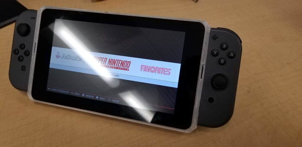
Retropie Switch
thingiverse
I have uploaded the step files for the main case, and don't guarantee that the hole locations for the screen are perfect, I had to open up the holes a bit to match the hole pattern on my screen, which I believe is an issue with my printer. The joycons will slide right in and fit snug. Any pi case that mounts through the bottom of the case should work with the main case, as the mounting holes are the same as the Pi. This is a work in progress, so feel free to modify. I have only tested the battery life to ~1:15min, but theoretically it should go further. I recommend using a better lipo charger if you know of one, these cheap chinese ones are not great. This setup will power the pi up to 3A, using my charge doctor it pulls ~2.5A. Make sure your battery can support this, and have a charger that can support charging and the Pi together. It is a UPS, so you can plug and unplug the pi without it powering down. I don't have a shutdown button yet, the case has one but I just haven't set it up, the latching microswitch is to turn off the 5v step-up regulator for a total shutdown to save the battery. Let me know if you have any suggestions for improvements or have any questions! Both Joycons work as one, and I do not have two-player mode setup yet. Follow this tutorial to get you started: https://github.com/DP-INVENTIONS/RASPSWITCH. You will have to make modifications to the button layouts though. Charging circuit: http://www.electrobob.com/5up-simple-5v-ups/ MORE DETAILS ON CHARGING CIRCUIT: I finally have a battery solution that works, these things are such a pain in the ass to battery power. The biggest issue I ran into was over-current protection on most 5V equipment is 1 or 2 amps. What you need: * Pololu 5V Step-Up Voltage Regulator U3V70F5 to step the battery voltage up to 5.2v. * An unprotected battery of your choice that is at least 2500mAh. I use a 5000mAh lipo that I removed the protection board from. I guess there is something I don't understand about LiPo batteries. It says it's rated at 1C discharge, but the protection board cuts out at 2A. Shouldn't it be 5 in my case? IDK, it's easy enough to add external protections. * TP4056 charging board for the lipo, you need to wire it up to bypass the internal over-current protection though. So use the battery input pins as your output as well. * Two schottky diodes that can handle the current. I used 1N5822 diodes. * Some beefy wire. Follow this circuit: http://www.electrobob.com/5up-simple-5v-ups/. The only things I would change are to wire in a push-button switch for shutdown, and add some extra padding on the back of the case. Parts needed: * Raspberry Pi 3 * Aluminum case from Meowbit (https://meowbit.com/aluminum-case-for-raspberry-pi-3/) * 12-inch flex cable for screen (https://www.amazon.com/gp/product/B00I6LJ19G/ref=ppx_yo_dt_b_asin_title_o07_s00?ie=UTF8&psc=1) * TP4056 charging board for the lipo (https://www.amazon.com/gp/product/B06XCXPY86/ref=ppx_yo_dt_b_asin_title_o00_s00?ie=UTF8&psc=1) * 5000mAh Lipo battery * Pololu 5V Step-Up Voltage Regulator U3V70F5 (https://www.pololu.com/product/2891) * 2x 3A schottky diodes, if you don't have any, then just buy a big assortment pack (https://www.amazon.com/gp/product/B01MCY9BWY/ref=ppx_yo_dt_b_asin_title_o07_s00?ie=UTF8&psc=1) * Micro USB breakout board (https://www.pololu.com/product/2586) * Protoboard (this makes it easier to do a clean job with the internal wiring) * Adafruit 2.5w amplifier (https://www.amazon.com/gp/product/B00PY2YSI4/ref=ppx_yo_dt_b_asin_title_o09_s03?ie=UTF8&psc=1) * Mini metal speaker (https://www.amazon.com/gp/product/B00N4YSRRC/ref=ppx_yo_dt_b_asin_title_o09_s01?ie=UTF8&psc=1) * 22-gauge silicone wire * 1x latching microswitch
With this file you will be able to print Retropie Switch with your 3D printer. Click on the button and save the file on your computer to work, edit or customize your design. You can also find more 3D designs for printers on Retropie Switch.
