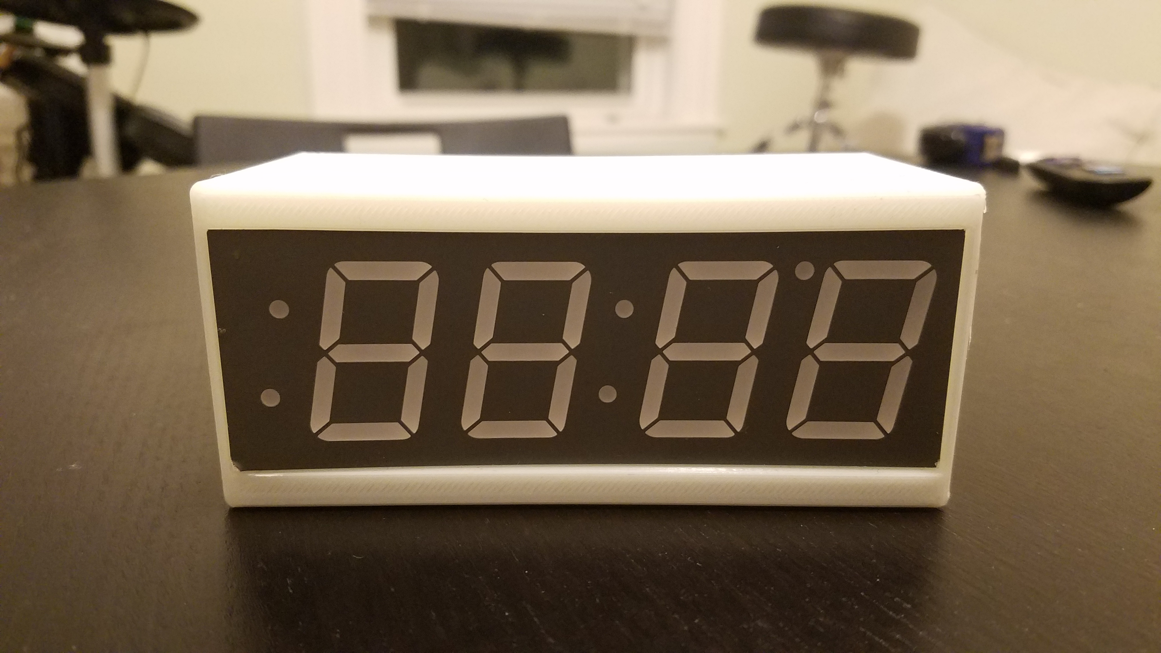
Raspberry Pi Zero Clock
myminifactory
I Know What You're Thinking: A Pi Zero Clock? Isn't a Zero Overkill for a Clock? I think not. With the internet at our fingertips, why settle for just telling time when we can do so much more? Imagine a clock that automatically adjusts across time zones based on its IP address or one that tracks your latest Amazon order. For me, it's about staying informed - like knowing exactly when the next subway train is arriving at my stop. Building this project requires some soldering skills, but all components are off-the-shelf and easily available. If you're up for the challenge, grab these materials: * A 1.2" 7-segment display from Adafruit in your preferred color * A Raspberry Pi Zero and supported power cord * Female to female jumper wires * A small WiFi dongle (preferably one that doesn't require compiling a module) * For non-press-fit versions: M2.5 screws and 3mm spacers There are two clock designs included in this project: the original features a removable backplate requiring M2.5 screws and spacers, resulting in a more visually appealing clock with hidden seams at the back and corners, and vertical layers. The press-fit version requires no screws, featuring a bezel on the front of the clock, but splits the clock horizontally instead. If you're an EE whiz, you can simplify the project by buying just the display and resistors, skipping the I2C backpack altogether and opting for protoboard or even posterboard to hold the clock. You could also snag a cheap display from Ebay or Alibaba and adjust the dimensions in the SCAD file. Setting up a Pi Zero with WiFi is an adventure; I recommend grabbing a starter kit if you don't have the necessary parts, doing a NOOBS graphical installation, or attempting a regular Raspbian installation over serial. For my WiFi configuration, I used wpa_supplicant. Since the Pi Zero can't support the power draw of a WiFi dongle over USB, you'll need to apply the wifi patch hack to get it to run off the main USB power. This means you won't be able to plug anything else into that USB port, so beware! Construction: My setup might not work on your machine due to tight tolerance designs. I highly recommend measuring your display and comparing the values to those at the top of the SCAD file, regenerating as necessary, or breaking out the X-acto knife and sandpaper for a more manual approach. For a general guide on enabling I2C and using the backpack with a Raspberry Pi, follow this tutorial. Here are some wire setup pictures: * Connect +5V and V_IC to 5v on the Raspi (pins 2 and 4) * Connect GND to ground (pin 6) * Connect SDA and SCL to the SDA and SCL GPIO pins on the Pi (3 and 5 respectively) Adafruit provides example Python scripts in their tutorial to get you started. That's it! Let me know if you have any questions.
With this file you will be able to print Raspberry Pi Zero Clock with your 3D printer. Click on the button and save the file on your computer to work, edit or customize your design. You can also find more 3D designs for printers on Raspberry Pi Zero Clock.
