Raspberry Pi HQ Camera Drone Gimbal
prusaprinters
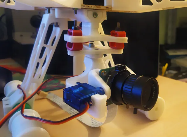
1. IntroductionHi! In this post, I will be covering everything about a simple drone gimbal I designed for the Raspberry Pi HQ Camera using the small & cheap SG90 servo motors. My goal was to design a simple-to-make and simple-to-use gimbal that can be made with some readily available parts. The gimbal has control over 2 axes, pitch, and yaw, which are the main ones needed for actually centering the camera on something. Down below you're able to find all of the STL files for printing as well as an F3D and STP file of the whole gimbal assemblies.2. Mechanical designBefore I get into the individual components of this gimbal, I'll show you a picture of the assembled gimbal and shortly explain the function of each component.The main gimbal assembly is made out of 5 parts. The gimbal itself can then be mounted to anything using 2 M3 screws from the top. In the picture above, you can see the quick swap rail mechanism I designed for it, which I will also cover later on.Let's get down to the main 5 parts of the gimbal:Gimbal adapter with rubber dampers - this is the part that connects the gimbal to the rest of the structure, whether that is a drone or something completely different.Gimbal mount - this is the part that is connected to the gimbal adapter with 6 rubber hose dampers to try and negate the effect of propellers on the camera.The main gimbal arm - this is the part that connects to the gimbal mount and serves as additional support for the yaw axis.Secondary gimbal arm - this is the part that holds the 2 SG90 servos as well as provides additional support for the pitch axis.Camera mount - this is the final part, it's essentially the pitch axis which has holes for mounting the Raspberry Pi HQ CameraBefore we get into the printable parts, we have the off-the-shelf parts.Off-the-shelf partsBesides the screws and nuts that are used for making this gimbal (M3 & M2.5 screws and nuts are required for assembling the whole thing), there are 3 off-the-shelf components that are needed, the Raspberry Pi HQ camera module and 2 SG90 servo motors.Here are the mock-ups I used for making the rest of the model.Printable partsNow I'll go part by part and explain how it's all supposed to go together. In the corner of each technical drawing, there are the slicer settings I recommend for each of the parts.Gimbal adapter with rubber dampersThis is the part that attaches the gimbal to the locking element which is then used to attach the whole thing to the rail of the drone. To try and eliminate the vibrations a bit, I put 2 pieces of rubber tubing as vibrations dampers on every corner of this adapter.Gimbal mountRight underneath goes the gimbal mount, which purpose is to attach to the gimbal adapter with the rubber dampers in between. The connection between those 2 will be free to absorb any bigger vibrations, while the connection between other parts of the gimbal and gimbal mount will be rigid.Main gimbal armRather than the whole gimbal just being attached through the axle of the SG90 servo, this arm will give 2 points of contact which will make the whole thing much more stable and stronger, than compared without.Secondary gimbal armThe secondary arm rotates inside the primary arm and carries both of the SG90 servos. In the middle of this part, there is an empty area left out for the Raspberry HQ Camera.Camera mountThe last part we have is the camera mount. It goes inside the secondary arm and attaches to one of the SG90 servo motors. It has 4 M2.5 holes used for securing the Raspberry HQ Camera to it.Gimbal assemblyWith all of the 5 main parts covered, here is how they all look assembled in CAD.And here is a 3D model view of the whole thing.Locking element & rail systemIn some of the pictures above you can see some additional parts on top beside the ones I already covered. These are the locking elements for the quick swap rail mechanism. Here is a closer look at those elements.You can see that this is made out of 2 parts. The bigger one has small teeth on the outside and is mounted to the gimbal using 2 M3 screws. The smaller part you can see is a wedge that is just big enough to hold an M3 nut inside. The idea is that the teeth start going outwards as we tighten the screw driving the wedge closer and closer. For this to work, we need an adequate rail for the system to lock into.In the picture above you can see how the rail is supposed to look. The rail you're seeing above is part of a DIY drone I worked on.3. Finished gimbalWith all of the parts covered now, we can take a look at what the final version of the gimbal looks like.The red things you can see in the picture are small slices of rubber hose I'm using as vibration dampers. I've printed everything using white PLA.Here is how it looks mounted to the drone I designed.If you're interested in more details when it comes to the drone, it's a completely open-source project that I've created and posted on element14. Here is a link to that project:https://community.element14.com/challenges-projects/project14/attackofthedrones/b/blog/posts/srd-1---3d-printed-drone-arduino-raspberry---june-11th-update---it-fliesThe only thing now left is to test out the gimbal.
With this file you will be able to print Raspberry Pi HQ Camera Drone Gimbal with your 3D printer. Click on the button and save the file on your computer to work, edit or customize your design. You can also find more 3D designs for printers on Raspberry Pi HQ Camera Drone Gimbal.
