Raspberry Pi 400 Alternate Bottom with 2.5" SSD Mount.
prusaprinters
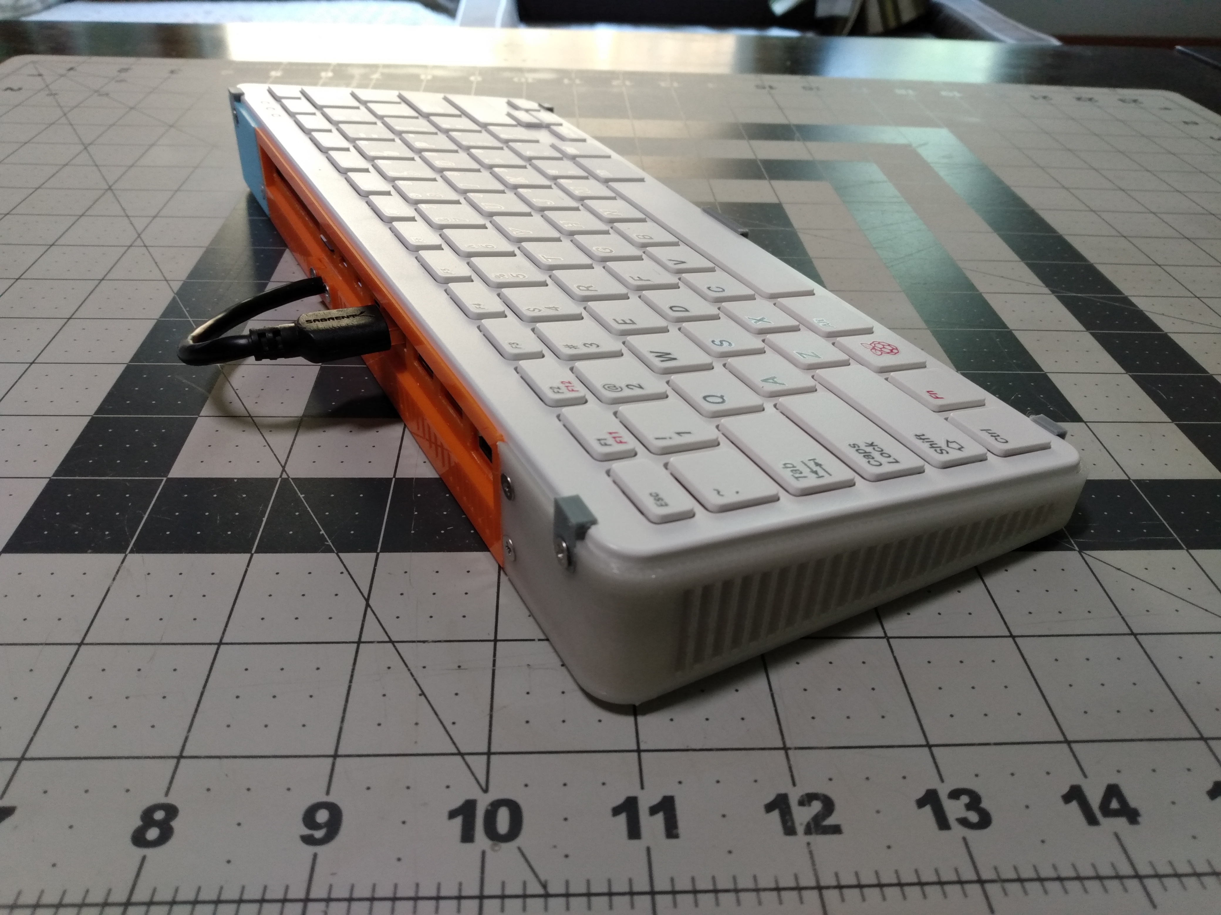
<p>EDITED: 11/1/2022 - I added a one piece bottom - BOTTOMasONEpieceREVISED-STL0 . I have not tested this personally as I don't have a printer big enough to fit it. If you print it, let me know how it goes and I might be able to adjust it if needed.</p><p> </p><p>EDITED: 9/4/2022 - I made a modified version of a couple of parts from this case. They allow for the use of a 180 degree USB adapter/jumper thing to eliminate the need to run the USB SATA cable outside of the case.</p><p> </p><p>https://www.printables.com/model/271101-update-for-my-pi-400-case-for-use-with-a-180-degre</p><p> </p><p>I made its own listing because it's this project already has a bunch of parts and a lengthy explanation. </p><p>---</p><p> </p><p>EDITED: 8/31/2022 - I added a .STP file of the whole assembly. It's called ASSYforEXPORT. It includes the VERY LOW DETAIL, but dimensionally accurate models of the keyboard and the motherboard.</p><p> </p><p>---</p><p> </p><p>This is a printable case bottom for the Raspberry Pi 400 that has more space than the injection molded original part and has room for addition equipment such as a 2.5" hard drive.</p><p>There are more pictures in this imgur gallery. https://imgur.com/a/kmlx8BG</p><figure class="image"><img src="https://media.printables.com/media/prints/264822/rich_content/9bf8ed6e-8db8-4af3-82b1-fa98794d298a/img_20220827_113438863.jpg#%7B%22uuid%22%3A%2260f2b4e2-55d5-4726-8606-6881e2337274%22%2C%22w%22%3A4160%2C%22h%22%3A3120%7D"></figure><figure class="image"><img src="https://media.printables.com/media/prints/264822/rich_content/cf0ba716-735b-4cd3-bef2-5b80d3dc9444/img_20220827_113443424.jpg#%7B%22uuid%22%3A%2254c94058-724a-4de6-821a-51af78c342e9%22%2C%22w%22%3A4160%2C%22h%22%3A3120%7D"></figure><figure class="image"><img src="https://media.printables.com/media/prints/264822/rich_content/45751f72-d3af-4821-802d-a250106b1d49/img_20220827_113500755.jpg#%7B%22uuid%22%3A%2268e4d83a-e03b-4b76-baeb-a9ce53de04b4%22%2C%22w%22%3A4160%2C%22h%22%3A3120%7D"></figure><p><br>This is intended to retain the original Raspberry Pi 400 keyboard, PCB, and heatsink panel.</p><p> </p><figure class="image"><img src="https://media.printables.com/media/prints/264822/rich_content/09a0d7cc-0283-4a91-badc-8d0a42d44652/img_20220827_113746888.jpg#%7B%22uuid%22%3A%22479a3491-e9f2-4640-baf5-70f68b6c3f71%22%2C%22w%22%3A4160%2C%22h%22%3A3120%7D"></figure><p> </p><p>It was designed to be printed on a typical sized hobbyist 3D printed such as a Prusa MK3 or Ender 3. Keeping the size of parts constrained to be able to be printed on a typical sized printer required many of the parts to be divided into smaller pieces and assembled with screws.</p><p> </p><figure class="image"><img src="https://media.printables.com/media/prints/264822/rich_content/2d5a3af5-b369-4bb9-81cc-19df19f62afc/img_20220827_115225908.jpg#%7B%22uuid%22%3A%22e4644ae1-ff65-4788-8dcb-688c6818e426%22%2C%22w%22%3A4160%2C%22h%22%3A3120%7D"></figure><p> </p><p>All of the parts shown in the pictures were printed on a completely stock Ender 3 V1, sliced in Cura 5, printed from PLA. </p><p> </p><p>All parts were sliced at .28mm layer height except where noted (mainly in the really small parts).</p><p> </p><p>I made a video explaining the hows and whats and whys of this project. The video is terrible, but if you have questions about this they might be answered in this video.</p><p> </p><figure class="media"><oembed url="https://www.youtube.com/watch?v=04bWkc73Mxc"></oembed></figure><p> </p><p>When I started designing this case, I oriented the models as though I was looking at the ports instead of looking at the keyboard as though I was going to use it. Therefor some items are named LEFT and RIGHT counterintuitively - that is they are LEFT and RIGHT as though you're looking at the back of the keyboard. Annoying, I know.</p><p> </p><p>The case consists of a left and a right bottom part, a left and a right structural part, an IO shield that makes up the back of the case, and some small clips and trim pieces to hold it all together.</p><p><br>Print time for all that parts, printed at .28mm layer height, with a .4mm nozzle, sliced in CURA, is approximately 20 hours. The bottom parts of the case are about 6.5 hours each, the IO shield is about 3 hours. The structure parts are about 90 minutes for both. And the miscellaneous trim and clips and joiner parts are another hour or so.</p><p> </p><p>Assembly requires: </p><p> </p><p>a quantity of 10 m2.5 x 6mm screws (I used Fastenal # QM2490006A20000)</p><p> </p><p>a quantity of 19 m3 x 6mm countersunk screws (I used Fastenal # XM2510008A20000)</p><p> </p><p>Both of these could be substituted for hex key style heads if you prefer, but the m3 screw MUST be countersunk in order to work properly, at least in positions where it screws through the bottom of the case (the SSD mount and two of the screws on the IO shield).</p><p> </p><p>I would HIGHLY RECOMMEND tapping the screw holes in the printed parts. Tapping the holes makes the screw connections stronger and greatly reduces the risk of stripping the screw holes or overtightening and damaging the components. </p><p> </p><p>I use an m3 tap and handle much like Amazon # B077HTXVR1 .</p><p><br>My m2.5 tap comes from Amazon # B08HZ3Z42G , but looking recently it seems Amazon sells an m2.5 tap and appropriate drill without buying a whole kit.</p><figure class="image"><img src="https://media.printables.com/media/prints/264822/rich_content/21f03a52-2243-408d-8216-f932a30c66ef/img_20220827_113451678.jpg#%7B%22uuid%22%3A%22c0c86929-5694-4391-8fb7-961f7a6b7efa%22%2C%22w%22%3A4160%2C%22h%22%3A3120%7D"></figure><p> </p><p>With a typical USB to SATA cable, the cable must run out of the case. There is just no way around it without adding more hardware.</p><p> </p><p>I have ordered a 180 degree USB A male to A female adapter ( diy-022-do on Ali Express) which will hopefully eliminate the need for the cable to run externally. I do not have this item on hand yet, but I have designed an experimental IO Shield part, designed from the less-than-complete dimensions on the Ali Express listing. There may be unforeseen problems with this design, use (and order the part from Ali Express) at your own risk.</p><p><a href="https://www.aliexpress.com/item/3256803052275966.html">USB 3.0 Connector 180 270 Degree USB Adapter USB A Male to Type A Female Gender 90 Degree Cable U Extension Converter|Computer Cables & Connectors| - AliExpress</a></p><figure class="image"><img src="https://media.printables.com/media/prints/264822/rich_content/832d0e80-d651-46ad-99a7-d2a7b5fd1a46/img_20220827_113538323.jpg#%7B%22uuid%22%3A%22c1f83199-d153-40fc-ae07-7c1078083025%22%2C%22w%22%3A4160%2C%22h%22%3A3120%7D"></figure><p> </p><p>There are provision in the bottom of the case for little rubber feet (Amazon # B073W1B3G1 or similar). These will keep the unit from sliding around, and also provide a couple of mm of clearance for aiflow to the grills on the bottom of the case.</p><p> </p><figure class="image"><img src="https://media.printables.com/media/prints/264822/rich_content/a82c918b-c0bc-4cee-83f7-289360de951c/img_20220827_120101936.jpg#%7B%22uuid%22%3A%2229c8775f-976a-463f-af84-e12cbb1ff381%22%2C%22w%22%3A4160%2C%22h%22%3A3120%7D"></figure><p>Additionally, there are holes under the feet that can be tapped for 3m screws for attaching feet/stands of your own design. Either for improved airflow through the grills, or for angling the keyboard to a more comfortable typing position.</p><p> </p><figure class="image"><img src="https://media.printables.com/media/prints/264822/rich_content/0846125d-8945-4b33-8477-fc8428c87bde/img_20220827_114503637.jpg#%7B%22uuid%22%3A%22bc67bdc0-bb35-4cc2-b8c7-a4756f27c9a1%22%2C%22w%22%3A4160%2C%22h%22%3A3120%7D"></figure><p> </p><p>The holes for mounting the rails that hold the drives are on a 100mm x 80mm rectangle. So if you wish to design a mount for a different size drive or perhaps an m.2 drive adapter you can do so.</p><p> </p><figure class="image"><img src="https://media.printables.com/media/prints/264822/rich_content/0fc46c43-5c47-4dc0-a02b-213690acf73f/img_20220827_114512128.jpg#%7B%22uuid%22%3A%224320d0fc-a689-47d2-b75a-ceebd5eff4a2%22%2C%22w%22%3A4160%2C%22h%22%3A3120%7D"></figure><p><br>Both bottom parts have these holes, so the drive can be mounted on either side. Offset drive mounts could also be created to possibly make room to mount two drives, dependent on the cables you use. </p><p> </p><p>There is a STP file included for the IO Shield so you can add additional holes for cables or resize the holes if you need to.</p><p> </p><p>For the IO Sheild with the cable hole, there is a cable strain relief part.</p><p> </p><p> </p><figure class="image"><img src="https://media.printables.com/media/prints/264822/rich_content/2dd89e91-14c6-4490-86bf-aa788252987b/img_20220827_114556652.jpg#%7B%22uuid%22%3A%22ca2ec75e-9140-4735-8efc-5a5b35dd5b85%22%2C%22w%22%3A4160%2C%22h%22%3A3120%7D"></figure><p> </p><figure class="image"><img src="https://media.printables.com/media/prints/264822/rich_content/f8953ace-5c23-4f3a-bc77-372934ee116b/img_20220827_114605352.jpg#%7B%22uuid%22%3A%220fece53b-7adb-4c9d-867e-5b2d88862ed6%22%2C%22w%22%3A4160%2C%22h%22%3A3120%7D"></figure><p> </p><figure class="image"><img src="https://media.printables.com/media/prints/264822/rich_content/39eadf64-39b9-43f2-a98d-53f274e04754/img_20220827_114754023.jpg#%7B%22uuid%22%3A%22a5e4bfe3-8ad2-45a1-9359-f20f9c3fc5ca%22%2C%22w%22%3A4160%2C%22h%22%3A3120%7D"></figure><p> </p><p>These grey clamp parts hold the keyboard in place. These will probably turn out better the smaller layer height you print them in. Such as .16 or .12mm. </p><p>It just just not possible, in my opinion, with my design skill level, to make a snap type enclosure as the original Raspberry Pi designed parts were. The snaps are too small, are too delicate with printed, to provide a secure closure and be able to be opened and then reused when you need to open the case to access the hardware. These clamps allow you open and reclose the case whenever needed without risk of breaking the printed parts.</p><p>There are front and rear clamp types. They are different. The ones for the front have an angle of less than 90 degrees (foreground in the pic below) and the rears have an angle of greater than 90 degrees (rear in the picture below)</p><figure class="image"><img src="https://media.printables.com/media/prints/264822/rich_content/ae0cc68e-8d3b-45eb-9d21-0ed898baaace/img_20220827_115642705.jpg#%7B%22uuid%22%3A%22f874d91d-da7d-421d-a6f0-f390fb3b103f%22%2C%22w%22%3A4160%2C%22h%22%3A3120%7D"></figure><p> </p><figure class="image"><img src="https://media.printables.com/media/prints/264822/rich_content/093812c9-ff9d-4b69-b095-772a795414cb/img_20220827_115001132.jpg#%7B%22uuid%22%3A%222ff1fda9-8afc-44cd-9508-2e448cecdbda%22%2C%22w%22%3A4160%2C%22h%22%3A3120%7D"></figure><p>The IO Shield prints with support built-in around the screw holes and the ports feature a sacrifical layer (a 1 layer thick membrane) that much be removed with a knife of cutters. This makes the supported area around the ports look much nicer as all the extrusion lines will be parallel. There is always an STP file of this part if you want to remove the built-in support parts or the sacrificial layer - you can and will also need to open a hole for your USB SATA cable.</p>
With this file you will be able to print Raspberry Pi 400 Alternate Bottom with 2.5" SSD Mount. with your 3D printer. Click on the button and save the file on your computer to work, edit or customize your design. You can also find more 3D designs for printers on Raspberry Pi 400 Alternate Bottom with 2.5" SSD Mount..