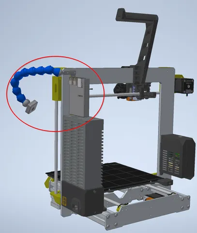
Raspberry Pi 3B case and camera holder for PRUSA I3 MK3S+
prusaprinters
I wanted to add a Raspberry Pi 3B with Octoprint to my PRUSA I3 MK3S+ including a cam for remote inspection during printing. For a clean installation I wanted the Pi to be mount to the frame of the Prusa. The cam should been mount to a flexible arm and held by the frame, too. After some tries I ended up with the following solution: Read the following instructions completely before you start assembling! These instructions are written in the order of “what I did” and not “in what order I did”! So you need to bring everything in order first.What you gonna needself cutting screws of type 2mm x 8mm length - F - Z (AliExpress https://www.aliexpress.com/item/4000768247074.html; 200pcs for 2,39€ incl. shipping).500mm plastic flexible Water Oil Coolant Pipe 3/8 inch=16mm (AliExpress https://www.aliexpress.com/item/4000295362127.html; 3.15€ incl. shipping)3A 24V-to-adjustable DCDC converter (https://www.aliexpress.com/item/1005001901305790.html; 1.80€ incl. shipping)RaspberryPi 3B + SD cardRaspberryPi cam V2.1RaspberryPi cam cable 50cm (AliExpress https://www.aliexpress.com/item/1005001636578419.html; 1.80€ incl. shipping)power cable; ~1m; 2x0.50mm²~5 Zip ties (prusa spare parts)shrink hose for DCDC; diameter:19..21mm; length:~40mm2 screws M3x20 (Prusa spare parts) multimeter to adjust 5.5V RPi supply voltage of DCDCphillips (cross) screw driverdepending on the precision of how your printer prints holes you might need the following drills:3.2mm for 2 holes holding the RaspberryPi3BCoverBack to the frame1.8mm for the holes of the 2x8mm self cutting screws 3D printed parts1x RaspberryPi3BCoverTop1x RaspberryPi3BCoverBackprint with 10 perimeters to give the arm to the hose sufficient strength1x RaspberryPiCamV2_1CaseFront1x RaspberryPiCamV2_1CaseBack1x RaspberryPiCamV2_1CaseJoint1..3x FFC_Clampprint with 10 perimeters to get sufficient strengthMechanical stuffFirst there was the RPi 3B case. It consisted of the lower part (RaspberryPi3BCoverBack) and the upper part (RaspberryPi3BCoverTop). The Pi was in-between both case parts. All three parts were held together by 4x self cutting screws of type 2mm x 8mm length - F - Z.Before mounting them together I had to install the DCDC converter first (see below in Electric stuff section) and the RPi camera cable.=====================================================For mounting the RPi to the frame I replaced the 2x original M3x10 screws of the right upper Z axis holder by 2x M3x20 and added a hex nut from the RPi side.=====================================================Next I ordered a 500mm plastic flexible Water Oil Coolant Pipe 3/8 inch=16mm, removed the nozzle and the threaded part (orange) and attached it to the RPi holder (see picture above). The pipe elements grip like hell and keep your cam in the desired position.=====================================================For the RPi cam I printed (from left to right)RaspberryPiCamV2_1CaseJointRaspberryPiCamV2_1CaseBackRaspberryPiCamV2_1CaseFrontFirst I stuck the RaspberryPiCamV2_1CaseJoint into RaspberryPiCamV2_1CaseBackand second I used 1x 2x8mm self cutting screw to tighten both together.In step 3 I attached the 50cm raspberry pi cable to the RPi camera.Finally I used 4x 2x8mm self cutting screws to sandwich the RPi cam between the RaspberryPiCamV2_1CaseBack and the RaspberryPiCamV2_1CaseFront=====================================================With the FFC_Clamp you can fix the cable to the flexible hose. Clip it to the hose and feed the cable through the slot. After printing the cable slot might be closed with squeezed plastic. I took a knife to cut it open.Electric stuffFor a clean installation I decided to supply the RPi by the 24V of the printer. For this I ordered a 3A 24V-to-adjustable DCDC converter. I selected an adjustable device to be able to set the voltage to a level the RPi will be happy with (5.5V).=====================================================The DCDC will be located also in the RPI case next to the CPU. It will lay there loose, held just by the cables.I took the DCDC and soldered a long cable (50cm) to its input (right side in picture) and a short cable (10cm) to its output (left side in picture). Next I adjusted the output voltage to 5.5V (USB max. allowed).After that I put a shrink hose around the PCB for isolation.I made a knot to the long cable in order to get a strain relief which will get stuck between the two USB connectors. The cable was laid between the two USB connectors where it leaves the case.The short cable was routed to the to back side of the RPi and directly soldered to PP5=GND and PP2=+5.5V. The long 24V DCDC cable was laid together with a 75cm USB cable along the Prusa printer upper frame (where the spool holder is attached) and fixed with spare Zip Ties (3x). Don't forget to route around the spool holder, if you use it!The USB cable was plugged into the motor driver board.The 24V cable was fed like the other cables into the motor driver board case from below and screwed together with the 24V cables from the main power supply module.The Zip tie on the vertical frame element (right in picture) must be zipped very tightly to avoid collisions with the X axis when it moves up and down.
With this file you will be able to print Raspberry Pi 3B case and camera holder for PRUSA I3 MK3S+ with your 3D printer. Click on the button and save the file on your computer to work, edit or customize your design. You can also find more 3D designs for printers on Raspberry Pi 3B case and camera holder for PRUSA I3 MK3S+.
