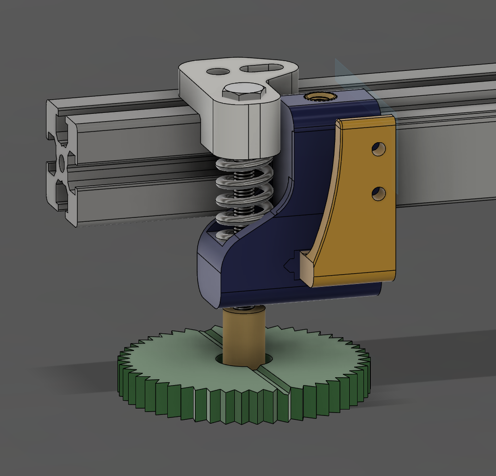
Railcore XRAT 2.0: Absolute Overkill Edition (X Rail Alignment Tool)
prusaprinters
<p>This is a major redesign of the <a href="https://www.thingiverse.com/thing:3499474">XRAT (X Rail Alignment Tool)</a> for the Railcore II.</p> <p>The basic principle is the same and the same operating instructions apply, but there are a number of improvements based on feedback from the community:</p> <ul> <li>Inclusion of an X endstop mount allowing for permanent installation on the printer</li> <li>The rail is under spring tension to help minimize the chance of the rail hanging when lowered.</li> <li>The end caps are locked to the ends of the rail via a set screw.</li> <li>The adjustment drive has been moved beneath the rail to allow better compatibility with Magnum pulleys</li> <li>An optional press fit thumb wheel is included to assist making finer adjustments. Each tooth on the wheel is set at 7.2 degrees, corresponding to 0.01mm of adjustment (i.e., well beyond what should be reasonably expected in terms of repeatable or measurable, but a decent baseline reference).</li> </ul> <p>Each rail-attached part has an A and B variant. If the rail is viewed from the center of the printer, A corresponds to the left hand side of the rail while B is for the right. There are additionally standard, long, and short variants of the endstop mount.</p> <p><strong>Parts required for a printer in the default X minimum endstop configuration:</strong></p> <ul> <li>1x Endcap A</li> <li>1x Endcap A (Endstop)</li> <li>2x Endcap B</li> <li>2x Top Cap A<em>or</em> 2x Halo Magnum Top Cap A</li> <li>2x Top Cap B<em>or</em> 2x Halo Magnum Top Cap B</li> <li>1x Endstop</li> </ul> <p><em>Optional:</em></p> <ul> <li>4x Thumbwheel</li> </ul> <p><strong>Additional hardware required:</strong></p> <ul> <li>5x <a href="https://www.mcmaster.com/94459A130">McMaster P/N 94459A130</a> 4.7x4.3mm threaded heat-set inserts</li> <li>4x Bed leveling springs with brass adjustment knob - Fairly generic, available from numerous suppliers. Key specs to look for are 7mm OD 20mm Spring, M3x40mm drive screw.</li> <li>8x M3 nuts, 4 per front and rear top extrusion channel.</li> <li>8x M3x8 bolts</li> <li>5x M3x3 or M3x4mm grub/set screws. Larger screws can be used, but the design intent is to secure the parts with recessed grub screws.</li> </ul> <p><strong>Installation instructions:</strong></p> <ul> <li>Install one heat-set insert each into the hole above the rail profile of both the A and B endcaps. Install two heated inserts in the endstop end cap. The second insert goes into the additional hole on the bottom of the part.</li> <li>Loosen the rails and push them over toward the stepper motor side of the printer.</li> <li>Press the appropriate end caps on to the idler side of each rail. This will be an<em>extremely</em> tight fit, by design, and will likely require a fair amount of pressure the first time an end cap is installed.</li> <li>Drop a spring into the spring cup of the end cap.</li> <li>Place the appropriate top cap over the spring. Loosely secure the top cap to the extrusion using 2x M3x8 bolts.</li> <li>Insert M3x40 drive screw through the hole in the top cap and down through the end cap.</li> <li>If using the optional thumb wheels, press the printed part onto the brass knob at this point.</li> <li>Thread adjustment knob on to the end of the 40mm drive screw.</li> <li>Push the rail toward the idler side of the printer and install the remaining end caps.</li> <li>Install the endstop switch on to the printed endstop mount.<strong>NOTE:</strong> The switch actuator<em>must</em> be on in the upper position to activate correctly.</li> <li>Slide the assembled end stop mount into the corresponding channel on the face of the end cap. There is a small notch at the rear of the channel that should allow you to insert a 1.5mm hex key or pick to push the mount out if the initial fit is too tight to make adjustments.</li> <li>Move the print carriage so the printer nozzle is aligned with the desired X0 point. Adjust the endstop mount so that the switch is engaged on the X carriage. One of the mount variants may be required if there is not sufficient travel with the standard mount.</li> <li>Insert an M3 grub screw into the top insert of each end cap and secure the end caps to the rails.</li> <li>Insert an M3 grub screw into the bottom insert of the endstop end cap and secure the X endstop mount in place.</li> <li>Tighten down the rails. You are now ready to begin aligning the X rails.</li> </ul> <p><a href="https://a360.co/2Ag3s5Y">Full Fusion 360 file available here</a>.</p> <hr/> <p>Changelog:</p> <ul> <li>2020-06-07: Initial release</li> <li>2021-01-30: Uploaded Halo Magnum Top Cap variants. These are slightly thinner to help provide additional clearance on printers using the Halo+Magnum combination.</li> </ul> <h3>Print Settings</h3> <p><strong>Printer:</strong></p> <p>Railcore II 300ZL</p> <p><strong>Rafts:</strong></p> <p>No</p> <p><strong>Supports:</strong></p> <p>No</p> <p><strong>Resolution:</strong></p> <p>.02</p> <p><strong>Infill:</strong></p> <p>70</p> <p><strong>Notes:</strong></p> <p>Print parts as-oriented. Supports not required, gaps are intended to be bridged.</p> <p>The end caps in particular have very tight dimensional tolerances. Prefer underextrusion to over extrusion.</p> Category: 3D Printer Parts
With this file you will be able to print Railcore XRAT 2.0: Absolute Overkill Edition (X Rail Alignment Tool) with your 3D printer. Click on the button and save the file on your computer to work, edit or customize your design. You can also find more 3D designs for printers on Railcore XRAT 2.0: Absolute Overkill Edition (X Rail Alignment Tool).
