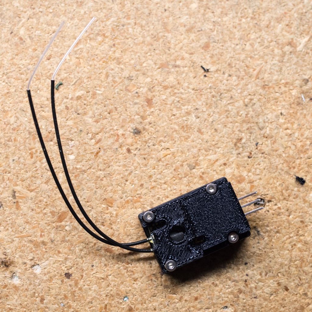
R-XSR Hard Case
thingiverse
This is a challenging scenario for the R-XSR, particularly when you need more mechanical reliability. Consider a larger RC plane or helicopter as an example. The design mechanically secures both the picoblade connector and the antennas while providing two secured servo connectors. In the diagrams, note the burgundy-colored 1.5mm foam padding. This is necessary to hold the R-XSR and antennas in place without damaging any components. The foam pad over the picoblade connector is intended to keep it plugged by form-fitting over the connection. The pins are 2.54 mm double row right angle connectors. These are soldered to a perf board and then to the pico blade connector. You will want to choose one side or the other and solder the two ground pins together (I suggest the side that aligns with the ground pin on the picoblade). The middle pins are for VDD, you will generally want to solder these together as well. The remaining two pins are for whatever you want. Generally, you would use one of these for S-BUS (or inverted SBUS which you can get from the board, Google "inverted sbus r-xsr" to learn more) and one for smart port. The four bolts are 8mm M2 bolts. There are holes in the case for several reasons: - At the bottom, to provide airflow (cooling) for the voltage regulator. - At the top - To allow the status lights to be visible - To allow access to the bind button - For additional cooling
With this file you will be able to print R-XSR Hard Case with your 3D printer. Click on the button and save the file on your computer to work, edit or customize your design. You can also find more 3D designs for printers on R-XSR Hard Case.
