Quick fit carriage system
thingiverse
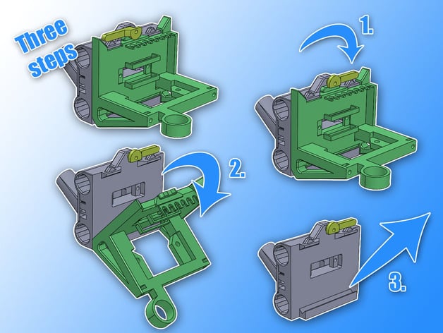
It seems like you've provided a detailed guide for assembling and customizing a 3D printer, specifically focusing on wiring and connector placement. Here's a reorganized version of your text with added headings for better readability: **Wiring Carefully** Careful with the wire layout: The wires on the opposite connector are mirrored. Keep a clear head. Triple check the layout of the wires! Also check for undesired short circuits between the wires! You could kill your board, motor or sensor. **SUB-D Connector in General** Ensure that both opposite connectors are fixated at the same height (M3 holes have some play). If you wish, you can even keep the connector on the tool-head-side slightly loose by using soft rubber washers on the proper side. **Base Part** Connect all required cables to the not-powered(!) board, arrange them, tie them together temporarily and cut them at the position of the print head. If your connectors are small and fit though the back-cover-tube: Remove the cables from the board. Solder the cables to the female connector and use thermal shrink tubing. Put the cables from the flat-side through the base part and the back-cover. If your connectors are big and don't fit though the back-cover-tube: Pull the cables though the cover and the base part. Solder the cables to the female connector and use thermal shrink tubing. Attach the connector with 2 20mm M3 screws and 2 nuts, place the cover and fixate it with 2 washers and 2 nuts. Connect cables to the board. Use a M3 screw, 2 washers and a nut to fixate the lever to the base part. **Extruder-Part** I'd suggest to use 5 additional Molex connectors to be able to disconnect the extruder from the plate to change the nozze or for other reasons. I used 3 2pin connectors for the 2 fans and the thermal sensor, a 3pin connector for the leveling probe and a 4pin connector for the 2 wires of the hotend heater. Solder the wires to the various connectors and then to the SUB-D connector. Push the cables and connector from the flat side into the SUB-D connector hole. Fixate the SUB-DD connector with approximately 6mm short M3 screws. You'll probably have to cut the screws. Fixate the extruder, the fan duct and the sensor. **Mill-Part** Solder a 100k Ohm resistor between the pins to simulate a thermal sensor. (If you use my circuit and a Z-probe solder a short circuit between a connected GND pin and the Z-sensor pin. Be careful, connecting anything else (12V, fan or motor pin) to the Z-sensor pin will kill your Microcontroller on the board.). Fixate the SUB-D connector from the flat-side into the hole with 2 M3 screws. Put both mill parts together and fixate them with 2 M3 screws and nuts. Use 2 M3 screws, nuts and washers to clamp the rotary tool. **Custom-Part** Solder a 100k Ohm resistor between the pins to simulate a thermal sensor. (If you use my circuit and a Z-probe solder a short circuit between a connected GND pin and the Z-sensor pin. Be careful, connecting anything else (12V, fan or motor pin) to the Z-sensor pin will kill your Microcontroller on the board.). Fixate the SUB-D connector from the flat-side into the hole with 2 M3 screws. **Connector** It might be necessary to use a pliers to bend the skirt of the male connector a little outwards. In such a way the connectors will easier mate. **G-Code for Homing** This code requires the mechanical Z-endstop and sensor-endstop being wired in series. The homing is performed after(!) heating the bed and hotend. ; ### mechanical home ### G28 ;home Z with meachnical endswitch ; ### set temperatures ### M106 S255; fan on, starts cooling of nozzle M140 S[first_layer_bed_temperature] ;set bed temperature M190 S[first_layer_bed_temperature] ;wait for bed temperature M104 S[first_layer_temperature] ;set extruder temperature M109 S[first_layer_temperature] ;wait for extruder temperature ; ### sensor home ### G1 Z6 F180 ;lift to inactive sensor height G1 X127.5 Y168 F6000 ;move sensor to exact center G28 Z ;home Z with sensor G92 Z3.95 ;adjust this height difference of sensor and nozzle G1 X70 Y0 Z0 F6000 ;move away from print bed ; ### prepare filament ### G92 E0 ;zero the extruded length G1 E8 F100; extrude filament G92 E0 ;zero the extruded length again G4 P500 ;wait for filament to feed through G28 Z ;home Z axis
With this file you will be able to print Quick fit carriage system with your 3D printer. Click on the button and save the file on your computer to work, edit or customize your design. You can also find more 3D designs for printers on Quick fit carriage system.
