Pump Bracket
grabcad
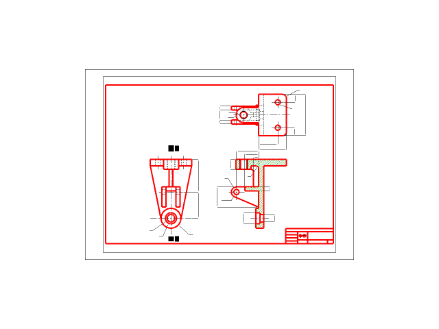
Designing a pump bracket involves creating a 2D CAD drawing that accurately represents its dimensions and layout. To begin, create a new drawing in AutoCAD by selecting File > New. Choose a suitable unit system and set the scale to match your project requirements. Draw the base of the pump bracket using the RECTANG command. Enter the desired length and width values, then press Enter to confirm the rectangle. Next, draw the vertical supports using the LINE command. Start at the bottom edge of the rectangle and extend upwards to create the first support. Repeat this process for each additional support, adjusting their positions as needed. Now, add the horizontal members between the vertical supports using the LINE command again. These will provide stability and rigidity to the bracket. Draw the mounting holes using the CIRCLE command. Enter a radius value that matches your screw or bolt size, then press Enter to create the hole. Add any additional features such as reinforcement plates or stiffeners by drawing new shapes with the POLYGON or RECTANG commands. Finally, add text labels to identify each component of the pump bracket. Use the MTEXT command to enter the label text and set its position using the MOVE command. Save your 2D CAD drawing by selecting File > Save As, giving it a meaningful file name that includes the project title and version number.
With this file you will be able to print Pump Bracket with your 3D printer. Click on the button and save the file on your computer to work, edit or customize your design. You can also find more 3D designs for printers on Pump Bracket.