Prusa i3 MK3 PiCam v2 X-Axis Motor Mount
prusaprinters
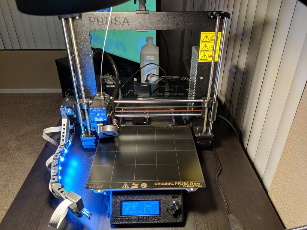
<h3>Prusa i3 MK3 PiCam v2 X-Axis Motor Mount</h3> <h3> What is this?</h3> <p>The goal here is to mount a Raspberry Pi Camera v2 to the X-Axis motor of the Prusa Research Prusa i3 MK3. This will allow the camera to move up the Z axis as printing, which should make for nice time lapse videos and allow a visual of the extruder while checking the live feed to look for potential issues.</p> <p>The arm is thickened significantly compared to others to allow for a couple of ~10mm wide (so a total of ~20mm wide) LED light strips to be attached directly to the arm. This should provide a much more even casting of light across the printed part.</p> <h3> Where did it come from?</h3> <p>I like the idea of the X axis motor mounted camera arm from <a href="/dragsterbox/about">dragsterbox</a> <a href="https://www.thingiverse.com/thing:2956323">here</a> and the arm extender from <a href="/Mososokruppe/about">Mososokruppe</a> <a href="https://www.thingiverse.com/thing:3042406">here</a>, and it's currently printed out and ready to go for my use (I printed a couple of Mososokruppe's extenders actually), just waiting on a PiCam ribbon I ordered that (should) be long enough to show up. While I was test fitting the parts I thought about how the print area will be lit, and while goofing around with my desk lamp realized some LED light strips might make the difference I'm looking for.</p> <h3> What's the plan here?</h3> <p>The cut outs in the arm are intended for zip ties to keep the LED strips in place (I never trust the stickiness of the tape on the back of these long term), although it should help reduce the mass of the arm a bit, too. I threw together a pretty generic mounting bracket system to connect the arms together: a couple holes for using screws and nylock nuts. An M3 screw should work for connecting each arm together, 16 to 20mm long. I considered placing an M3 nut cut out but decided against it, as leaving it "free floating" should allow for much easier minor adjustments to the camera angles. I kept dragsterbox's PiCam enclosure and rotating mount, and used the shape of his mounting arm as a guide for the main arm here.</p> <h3> Parts:</h3> <p>1.<em>Main arm:</em> Required, mounts to the X Axis motor so the camera moves up the Z axis as printing.<br/> 3.<em>Extender:</em> Optional, I prefer the camera being a bit further out from the bed and closer to the front left corner of the bed.<br/> 5.<em>Camera mount arm:</em> Required, this is where the camera sits. This arm is shaped a bit differently on the end to allow dragsterbox's enclosure and rotating mount.<br/> 4:<em>Camera case and mount:</em> This is dragsterbox's enclosure and mount directly, including for ease of download.<br/> 5:<em>"Altogether":</em> A couple STL's of the parts for the arm all together (if you already have dragsterbox's stuff printed), and another of all the parts together.<br/> 7.<em>M3 20mm screws and M3 nylock nuts:</em> These will be used to connect the arm segments together. 16mm might work for some spots.<br/> 9.<em>LED Strips:</em> The LED strips I got are from Fry's, <a href="https://www.frys.com/product/6193639">Omni Lighting Systems Home Accent Series Kits</a>. I got a <a href="https://www.frys.com/product/6258050?site=sr:SEARCH:MAIN_RSLT_PG">Y split/extension cable</a> to go with it, and the plan is to route the extension cable around the back of the arms, down the frame, and out the back to it's control box/power adapter. Almost any LED strip of the right length should work here as long as it's flexible and 10-20mm thick. I'm doubling up on the 10mm strips to increase the amount of light. RGB definitely isn't necessary but a nice to have in my opinion as different color filament might look nicer with different lighting.</p> <ol> <li>Depending on where you mount your Pi, a decently long PiCam ribbon cable. Mine is 1 meter. Amazon link: ([<a href="http://a.co/d/ipKorKB)[http://a.co/d/ipKorKB](http://a.co/d/ipKorKB)%5Bhttp://a.co/d/ipKorKB">http://a.co/d/ipKorKB)[http://a.co/d/ipKorKB](http://a.co/d/ipKorKB)%5Bhttp://a.co/d/ipKorKB</a>)] I could have gone shorter, but I'd prefer having a tiny bit more slack than necessary than not enough.<br/> Notes</li> </ol> <hr/> <p>Rev1 parts keep the camera lower and provides an excellent view of the extruder. Rev2 brings the camera up high enough so it's looking down at the build plate more. Rev1 is great for checking a live feed to ensure things are printing right, Rev2 is better for timelapses. I can't help but recommend printing both, try them out and see how you feel about it.</p> <h3> Print settings</h3> <p>My Slic3rPE settings:</p> <p>For the arms: 3 perimeters, 30% infill. I want the arms themselves to be rigid. STL's should be setup so the arms print flat, which keeps the layer lines running in a way that should help reduce seperation due to vibrations and hold up to types of motion it should experience. No supports are necessary in this orientation, either.<br/> For the camera parts: I'd do 2 perimeters and 10-20% infill, whatever floats your boat (or 3DBenchy... eh? eh? Bad joke? K I'll see myself out)</p> <h3> What's pictured</h3> <p>To start, I didn't notice until after I started uploading the pictures of it mounted that one of the LED strips was off. It was plugged in wrong. Whoops! Fixed it, and you may guess but it's a good bit brighter now.</p> <ol> <li>Front view of camera with arm fully installed and functioning (ignoring that one LED strip that I didn't plug in right).</li> <li>Timelapse recorded with Rev1 installed: <a href="https://youtu.be/AeQpy1RO2DE">https://youtu.be/AeQpy1RO2DE</a></li> <li>Here you can see the slack in the PiCam ribbon at the joints better.</li> <li>Wider shot of the arm and my attempt at managing the cabling.</li> <li>I try to keep wiring as tidy as possible but the PiCam's ribbon doesn't like being tied up when moving up and down the Z Axis. I let it hang loose and tried to keep everything else tighter.</li> <li>Pictured during install, ths is my test fitting. </li> <li>To reduce confusion hopefully, here's the exact placement of each arm segment.</li> <li>Another picture during test fitting.</li> <li>I'm likely going to raise this camera mount position all the way up to regain that few millimeters worth of camera angle. I didn't think the LED strip would extend so far out with the slack I was hoping to give it at the joints but ultimately I prefer having lighting right under the camera to hopefully give it more direct lighting at what it's pointing at.</li> <li>This is testing the LED's to ensure they were working and also trying to route the cables as smartly as possible. These strips are bright enough I didn't notice only one was on.</li> <li>View from Octoprint Control tab during the first layer of my first print after installing.</li> </ol> <h3>Print instructions</h3><h3>Category: 3D Printer Accessories Summary</h3> <h3> Prusa i3 MK3 PiCam v2 X-Axis Motor Mount</h3> <h3> What is this?</h3> <p>The goal here is to mount a Raspberry Pi Camera v2 to the X-Axis motor of the Prusa Research Prusa i3 MK3. This will allow the camera to move up the Z axis as printing, which should make for nice time lapse videos and allow a visual of the extruder while checking the live feed to look for potential issues.</p> <p>The arm is thickened significantly compared to others to allow for a couple of ~10mm wide (so a total of ~20mm wide) LED light strips to be attached directly to the arm. This should provide a much more even casting of light across the printed part.</p> <h3> Where did it come from?</h3> <p>I like the idea of the X axis motor mounted camera arm from <a href="/dragsterbox/about">dragsterbox</a> <a href="https://www.thingiverse.com/thing:2956323">here</a> and the arm extender from <a href="/Mososokruppe/about">Mososokruppe</a> <a href="https://www.thingiverse.com/thing:3042406">here</a>, and it's currently printed out and ready to go for my use (I printed a couple of Mososokruppe's extenders actually), just waiting on a PiCam ribbon I ordered that (should) be long enough to show up. While I was test fitting the parts I thought about how the print area will be lit, and while goofing around with my desk lamp realized some LED light strips might make the difference I'm looking for.</p> <h3> What's the plan here?</h3> <p>The cut outs in the arm are intended for zip ties to keep the LED strips in place (I never trust the stickiness of the tape on the back of these long term), although it should help reduce the mass of the arm a bit, too. I threw together a pretty generic mounting bracket system to connect the arms together: a couple holes for using screws and nylock nuts. An M3 screw should work for connecting each arm together, 16 to 20mm long. I considered placing an M3 nut cut out but decided against it, as leaving it "free floating" should allow for much easier minor adjustments to the camera angles. I kept dragsterbox's PiCam enclosure and rotating mount, and used the shape of his mounting arm as a guide for the main arm here.</p> <h3> Parts:</h3> <p>1.<em>Main arm:</em> Required, mounts to the X Axis motor so the camera moves up the Z axis as printing.<br/> 3.<em>Extender:</em> Optional, I prefer the camera being a bit further out from the bed and closer to the front left corner of the bed.<br/> 5.<em>Camera mount arm:</em> Required, this is where the camera sits. This arm is shaped a bit differently on the end to allow dragsterbox's enclosure and rotating mount.<br/> 4:<em>Camera case and mount:</em> This is dragsterbox's enclosure and mount directly, including for ease of download.<br/> 5:<em>"Altogether":</em> A couple STL's of the parts for the arm all together (if you already have dragsterbox's stuff printed), and another of all the parts together.<br/> 7.<em>M3 20mm screws and M3 nylock nuts:</em> These will be used to connect the arm segments together. 16mm might work for some spots.<br/> 9.<em>LED Strips:</em> The LED strips I got are from Fry's, <a href="https://www.frys.com/product/6193639">Omni Lighting Systems Home Accent Series Kits</a>. I got a <a href="https://www.frys.com/product/6258050?site=sr:SEARCH:MAIN_RSLT_PG">Y split/extension cable</a> to go with it, and the plan is to route the extension cable around the back of the arms, down the frame, and out the back to it's control box/power adapter. Almost any LED strip of the right length should work here as long as it's flexible and 10-20mm thick. I'm doubling up on the 10mm strips to increase the amount of light. RGB definitely isn't necessary but a nice to have in my opinion as different color filament might look nicer with different lighting.</p> <ol> <li>Depending on where you mount your Pi, a decently long PiCam ribbon cable. Mine is 1 meter. Amazon link: ([<a href="http://a.co/d/ipKorKB)[http://a.co/d/ipKorKB](http://a.co/d/ipKorKB)%5Bhttp://a.co/d/ipKorKB">http://a.co/d/ipKorKB)[http://a.co/d/ipKorKB](http://a.co/d/ipKorKB)%5Bhttp://a.co/d/ipKorKB</a>)] I could have gone shorter, but I'd prefer having a tiny bit more slack than necessary than not enough.<br/> Notes</li> </ol> <hr/> <p>Rev1 parts keep the camera lower and provides an excellent view of the extruder. Rev2 brings the camera up high enough so it's looking down at the build plate more. Rev1 is great for checking a live feed to ensure things are printing right, Rev2 is better for timelapses. I can't help but recommend printing both, try them out and see how you feel about it.</p> <h3> Print settings</h3> <p>My Slic3rPE settings:</p> <p>For the arms: 3 perimeters, 30% infill. I want the arms themselves to be rigid. STL's should be setup so the arms print flat, which keeps the layer lines running in a way that should help reduce seperation due to vibrations and hold up to types of motion it should experience. No supports are necessary in this orientation, either.<br/> For the camera parts: I'd do 2 perimeters and 10-20% infill, whatever floats your boat (or 3DBenchy... eh? eh? Bad joke? K I'll see myself out)</p> <h3> What's pictured</h3> <p>To start, I didn't notice until after I started uploading the pictures of it mounted that one of the LED strips was off. It was plugged in wrong. Whoops! Fixed it, and you may guess but it's a good bit brighter now.</p> <ol> <li>Front view of camera with arm fully installed and functioning (ignoring that one LED strip that I didn't plug in right).</li> <li>Timelapse recorded with Rev1 installed: <a href="https://youtu.be/AeQpy1RO2DE">https://youtu.be/AeQpy1RO2DE</a></li> <li>Here you can see the slack in the PiCam ribbon at the joints better.</li> <li>Wider shot of the arm and my attempt at managing the cabling.</li> <li>I try to keep wiring as tidy as possible but the PiCam's ribbon doesn't like being tied up when moving up and down the Z Axis. I let it hang loose and tried to keep everything else tighter.</li> <li>Pictured during install, ths is my test fitting. </li> <li>To reduce confusion hopefully, here's the exact placement of each arm segment.</li> <li>Another picture during test fitting.</li> <li>I'm likely going to raise this camera mount position all the way up to regain that few millimeters worth of camera angle. I didn't think the LED strip would extend so far out with the slack I was hoping to give it at the joints but ultimately I prefer having lighting right under the camera to hopefully give it more direct lighting at what it's pointing at.</li> <li>This is testing the LED's to ensure they were working and also trying to route the cables as smartly as possible. These strips are bright enough I didn't notice only one was on.</li> <li>View from Octoprint Control tab during the first layer of my first print after installing.<h3>Print Settings</h3> </li> </ol> <p><strong>Printer Brand:</strong> Prusa</p> <p><strong>Printer:</strong> i3 MK3</p> <p><strong>Rafts:</strong> No</p> <p><strong>Supports:</strong> No</p> <p><strong>Resolution:</strong> .2</p> <p><strong>Infill:</strong> 30</p> <p><strong>Notes:</strong></p> <p>Perimeters: 3</p> <p>If you're printing this on a Prusa Mk3 like me, you shouldn't need any supports and .2 resolution should be fine. If you're printing on something else, you may need to plan accordingly.</p> <p>The parts for the camera itself can be printed with lower infill and perimeters. 15% and 2 should be good.</p> <h3> Post-Printing</h3> <p><strong>How to Install</strong></p> <p>You should not require supports to print this unless you change orientation. Besides maybe clearing stringing from the holes if your printer isn't tuned just right there should be no need for any real work here besides putting it together.</p> <p>I recommend putting the arm together and installing your PiCam before mounting it to your printer.</p> <ol> <li>Use a 16-20mm M3 screw and M3 nylock nut to connect the main arm to the extender, and another to connect the extender to the camera arm. Note: The extender is optional. I prefer it for removing the camera further from the print surface, giving a more full image of the print. Tighten the screws to a point where you can move the arms pretty easily but they mostly hold in place on their own.</li> <li>Insert a nylock nut into the camera rotating mount (the vaguely U-shaped piece). There's a M3 nut sized insert, I had to use pliers to get it in place. Insert a 16mm M3 screw from below the arm, tighten to the point where you can just rotate the camera.</li> <li>Now's a great time for a test fit. Take the front of the PiCam case (with the single square hole in the middle) and loosely mount it to the rotating camera mount. Just a single screw, don't put a nut on yet. Use a 16mm M3 screw to mount the main arm to your X-Axis motor or hold it in place by hand. For the best view long term I recommend getting the extruder roughly in the middle of the X axis. Take a peak through the front camera case's square hole and adjust the arms and camera until you're happy with how it's angled at the extruder. The idea of having it in the middle is most prints will be centered and you'll get the best view for most objects you print now without having to make lots of adjustments later. When you're happy with the angle of all arms and the camera tighten all the screws and nuts into place. I tried to tighten things to the point where they don't move unless I'm putting in some effort.</li> <li>If you didn't remove the arm to tighten the screws, go ahead and do so now so we can get your LED strip(s) in place. I recommend starting at the angle of the main arm, putting a single zip tie in place, then working towards the actual camera mount. Attempt to allow some give at the joints by letting some slack build up before putting the first zip tie on the next arm segment. Depending on your LED strip this might be easier or harder than it was for me, but it turned out ok. This will allow you to move the arms to make minor adjustments later without damaging the strips. You probably only need 2 zip ties per arm segment, just enough to hold things in place. Test your LED strips to ensure you didn't damage them in the mounting procedure.</li> <li>Depending on where/how you're mounting your Raspberry Pi, you can either mount the arm to the X Axis motor then the PiCam to the arm, or the PiCam to the arm then the arm to the X Axis motor. It might be easier to mount the camera with the arm off the printer or not. Up to you.</li> <li>You're basically done. Plug it anything that's not plugged in, move the axis' around to see how the arm's doing, check how it looks in Octoprint (I had to flip my camera horizontally and vertically on Octoprint, and I forgot to set it up in Octolapse before I started a print but I think you can rotate it there, too?), use a PiCam focus tool to get things looking good (I got mine to the point that I can read the text on the extruder motor), etc.<h3>How I Designed This</h3> </li> </ol> <p><strong>Tinkercad to the rescue</strong></p> <p>I loaded dragsterbox's parts into tinkercad, dropped in a couple boxes to reflect the size and angles needed, then cut his arm up so I'm using the bit that actually mounts to the X axis motor. You can see the tinkercad version here:</p> <p><a href="https://www.tinkercad.com/things/3wbxeGbQ4ZH"></a><a href="https://www.tinkercad.com/things/3wbxeGbQ4ZH">https://www.tinkercad.com/things/3wbxeGbQ4ZH</a></p>
With this file you will be able to print Prusa i3 MK3 PiCam v2 X-Axis Motor Mount with your 3D printer. Click on the button and save the file on your computer to work, edit or customize your design. You can also find more 3D designs for printers on Prusa i3 MK3 PiCam v2 X-Axis Motor Mount.