Proteus - an OpenSCAD slope soarer design
thingiverse
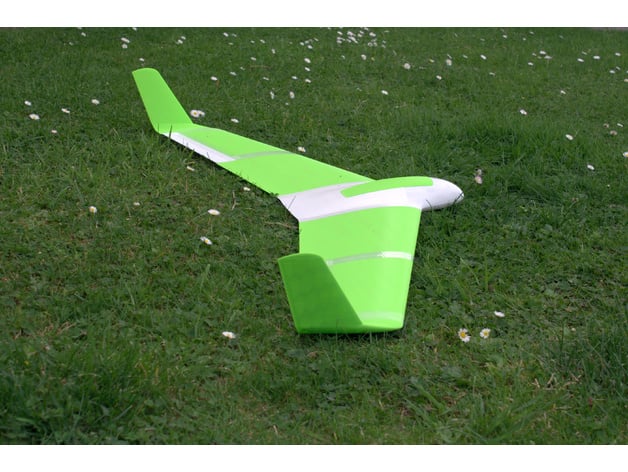
The text describes the design and construction of a 3D printed slope soaring aircraft, with a focus on its aerodynamic features, structural integrity, and ease of assembly. The author provides detailed instructions for printing and assembling various components, including the fuselage, wings, servos guards, and hatch. Some key points from the text include: * **Aerodynamic design**: The aircraft uses a moderately thin flying wing airfoil (MH-45) designed by Martin Hepperle, which is suitable for slope soaring and has good performance at likely wing loadings. * **Structural integrity**: The wings are supported by a carbon fiber tube spar, making them easy to replace if damaged. The fuselage is printed with a single perimeter and Simplify3D's Fast Honeycomb infill, resulting in a lightweight yet strong structure. * **Servo protection**: Aerodynamic guards protect the servos and linkages on landing, while also allowing for easy replacement of damaged parts. * **Assembly instructions**: The author provides detailed instructions for printing and assembling various components, including the fuselage, wings, servos guards, and hatch. Overall, the text provides a comprehensive guide to designing and building a 3D printed slope soaring aircraft with a focus on aerodynamic performance, structural integrity, and ease of assembly.
With this file you will be able to print Proteus - an OpenSCAD slope soarer design with your 3D printer. Click on the button and save the file on your computer to work, edit or customize your design. You can also find more 3D designs for printers on Proteus - an OpenSCAD slope soarer design.