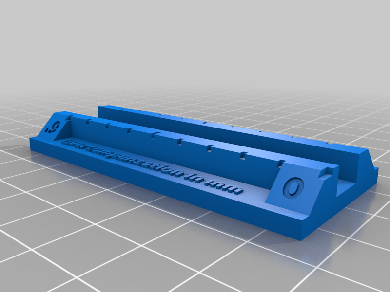
Printer Tolerance Calibrator
thingiverse
Please note: I haven't been able to test this in real life yet, so it might not work at all. Comments are appreciated! This calibrator makes it easy to measure how much tolerance is needed to create separate fitting parts. Instructions ---------------- 1. Make sure your extruder and stepper motors are calibrated, your bed is level, and you have a working setup. This calibrator is for fine-tuning pre-production, not initial calibration. 2. Slice and print both parts with the same filament and settings that you'll use to print your parts. 3. Remove any blobs or stringing from the printed part to make sure the surfaces where both parts touch are clean and even. 4. Insert the top part into the bottom part in the direction of the arrows until you feel resistance. Interpret Your Results ---------------------------- 1. If both notches line up with 0, no additional tolerance is needed for fitting parts. 2. If the Overcompensation-notch lines up with more than 0, remove material from your design to create fitting parts. The ruler ranges from 0 to 0.9mm, adjust accordingly. 3. If the Undercompensation-notch lines up with more than 0, add material to your design to create fitting parts. The ruler ranges from 0 to 0.9mm, adjust accordingly. See images for a visual explanation. Example ------------ Say you have a cylinder with an axial hole (r=10mm) and a rod (r=10mm) that's supposed to be inserted in the cylinder. You use the calibrator and get the following result: Overcompensation=0.13mm You would now enlarge the axial hole in the cylinder by 0.13mm or reduce the rod's radius by 0.13mm, and you should end up with fitting parts.
With this file you will be able to print Printer Tolerance Calibrator with your 3D printer. Click on the button and save the file on your computer to work, edit or customize your design. You can also find more 3D designs for printers on Printer Tolerance Calibrator.
