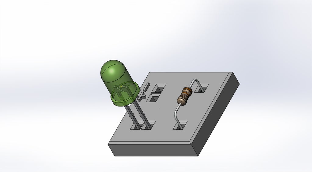
Print your own PCB - PROOF OF CONCEPT
prusaprinters
<p>This is a PROOF OF CONCEPT how to make your own "PCB" for THT components.<br/> It's just to show that it's possible to make a very crude "PCB" with a 3D printer.<br/> With some modification it is possible to add some of the larger SMD components.</p> <p>I love electronics, but i don't know how to etch my own PCBs and for my little projects I wanted to have something of my own. That's why i wanted to see if the idea of a 3D printed variation of a PCB is applicaple with a standard 3D printer.</p> <p> <figure class="media"> <oembed url="https://www.youtube.com/watch?v=QikAQDyuIuU&feature=youtu.be"></oembed> </figure> </p> <h3>Print instructions</h3><h3>Category: Electronics Summary</h3> <p>This is a PROOF OF CONCEPT how to make your own "PCB" for THT components.<br/> It's just to show that it's possible to make a very crude "PCB" with a 3D printer.<br/> With some modification it is possible to add some of the larger SMD components.</p> <p>I love electronics, but i don't know how to etch my own PCBs and for my little projects I wanted to have something of my own. That's why i wanted to see if the idea of a 3D printed variation of a PCB is applicaple with a standard 3D printer.</p> <p> <figure class="media"> <oembed url="https://www.youtube.com/watch?v=QikAQDyuIuU&feature=youtu.be"></oembed> </figure> </p> <h3> Print Settings</h3> <p><strong>Printer:</strong> DIY Mendel90 (Nevex)</p> <p><strong>Rafts:</strong> No</p> <p><strong>Supports:</strong> No</p> <p><strong>Resolution:</strong> 0.2</p> <p><strong>Infill:</strong> 13% Honeycomb</p> <h3> How I Designed This</h3> <p><strong>Idea</strong></p> <p>I love electronics, but i don't know how to etch my own PCBs and for my little projects I wanted to have something of my own. That's why i wanted to see if the idea to 3D print a variation of a PCB is applicaple with a 3D printer.</p> <p><strong>Concept</strong></p> <p>To make the idea into practice I wanted to start with a simple circuit: battery, LED and resistor.<br/> I placed the components as in the schematic and started drawing my test "PCB" in SolidWorks.</p> <p><strong>Test circuit</strong></p> <p><strong>First Design</strong></p> <p>I thought about how PCBs are made and so i thought about having all the connections on the lower side and no connection visible on the upper side.<br/> I had to design chamfered holes in order for the connections to be soldered to components, or the connections wouldn't be possible to acheive.</p> <p><strong>Chamfered holes and cut sections to make room for wires and soldered joints</strong></p> <p><strong>Second Design</strong></p> <p>Because I didn't like the idea to solder wires and melt the surrounding plastic (especially PLA), I thought about making wire connections just by friction, similarly like i did in my Solderless wire termination (<a href="https://www.thingiverse.com/thing:1381358">http://www.thingiverse.com/thing:1381358</a>).</p> <p>That way I could also hide the connections inside the plastic part, so I drew them in the middle section. Also, that way the connections wouldn't be available to make any shorts or be unintentionally damaged.</p> <p><strong>The holes could be a bit smaller :)</strong></p> <p><strong>Final desing: top and bottom look the same (connections are hidden inside the plastic part)</strong></p> <p><strong>Making the STL</strong></p> <p>After the drawing was made I exported and saved it as STL.</p> <p><strong>Here placed using the Simplify3D software.</strong></p> <p><strong>Modifying G-code</strong></p> <p>Because I needed my printer to pause at a certain height, so that i could be able to insert the wire connection, I thought about using Cura software with it's plugin PauseAtZ (<a href="http://wiki.ultimaker.com/CuraPlugin:_Pauseatz">http://wiki.ultimaker.com/CuraPlugin:\_Pauseatz</a>).</p> <p><strong>Cura layer view: pausing and moving extruder to position X=5cm, Y=5cm from origin</strong></p> <p>Because I don't use Cura at all, I just wanted to see what this plugin code does to the G-code to make the printer pause.<br/> I sliced the STL file, both in Cura and Siplify3D. I then compared the Simplify3D and Cura G-code as seen in the picture.</p> <p>When examining the G-code and much help from the Reprap wiki page (<a href="http://reprap.org/wiki/G-code">http://reprap.org/wiki/G-code</a>) and the G-code cheat sheet (<a href="https://thingiverse-production-new.s3.amazonaws.com/assets/87/b0/2c/f5/4c/CheatSheet.pdf">https://thingiverse-production-new.s3.amazonaws.com/assets/87/b0/2c/f5/4c/CheatSheet.pdf</a>), I was able to modify the Simplify3D code to my needs.</p> <p><strong>All of this could be also done if I would take a little bit of time to modify the original Python code of the plugin</strong></p> <p><strong>End result</strong></p> <p>At the end I was able to achieve what I was looking for - a printable PCB like circuit that WORKS!<br/> So, my thought of making small printable PCBs for THT components and chips in DIL packages (see my Solderless wire termination: <a href="https://www.thingiverse.com/thing:1381358">http://www.thingiverse.com/thing:1381358</a>) is very much acheivable with a little bit of work and patience.</p> <p>Of course it needs to be perfected, but the proof of concept has been acheived and I'm so very happy :)</p> <p><strong>Connection wires inserted while printing is paused</strong></p>
With this file you will be able to print Print your own PCB - PROOF OF CONCEPT with your 3D printer. Click on the button and save the file on your computer to work, edit or customize your design. You can also find more 3D designs for printers on Print your own PCB - PROOF OF CONCEPT.
