Pololu case for 3.5" Prusa touchscreen mod
prusaprinters
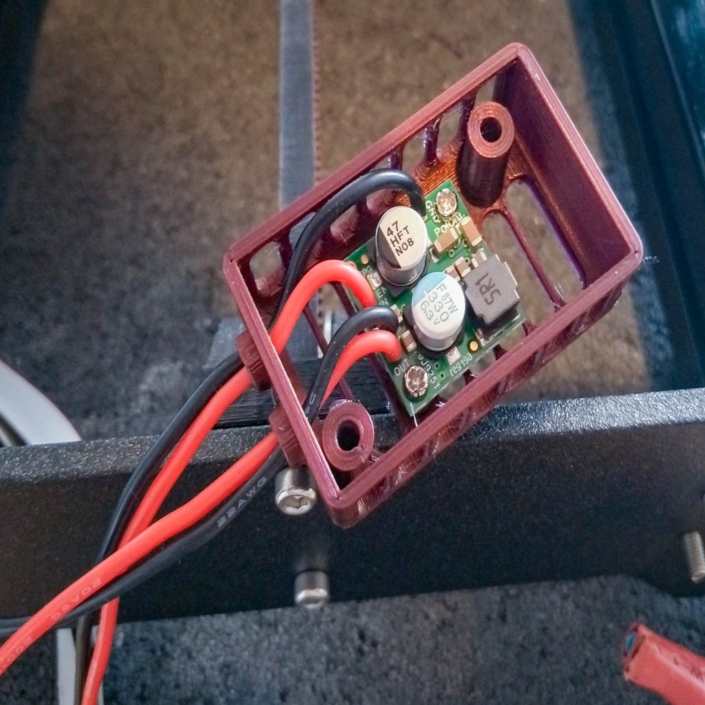
<p>This is a case to add the <a href="https://www.pololu.com/product/2858">Pololu D24V22F5 5V step-down converter</a> to the <a href="https://www.thingiverse.com/thing:3372513">3.5" touchscreen mod for the</a> Prusa i3 MK3.</p> <p>Parts needed:</p> <ul> <li><a href="https://www.pololu.com/product/2858">Pololu D24V22F5 5V step-down converter</a></li> <li>M2 x 6mm screw x 2 pieces for mounting the Pololu</li> <li>22 AWG wire (not any thicker, because otherwise it won't fit through the case). I went for silicone-jacketed wire in red and black.</li> <li><a href="https://github.com/PrusaOwners/prusaowners/wiki/MK3_Compatible_Parts">Spade connector to suit the #6 stud of the Einsy power connectors</a> x 2 pieces</li> </ul> <p>I printed mine in Prusament Mystic Brown PLA. Use the "0.2mm SPEED" preset.</p> <h3>Post-Printing</h3> <p>Prepare two power wires to piggyback onto the power connectors of the Einsy by soldering or crimping a spade terminal onto one end of both wires. Ensure that the power cable of your printer is disconnected, then loosen one pair of positive and negative power connectors on the Einsy and slide the spades underneath the washers, and tighten.</p> <p>Route the power cables along the bottom of the printer until they reach the front, like the LCD cables do. You can use the wire clips from the original mod to clip them to the left side of the front extrusion instead of bundling them with the LCD cables.</p> <p class="detail-image"><img src="https://cdn.thingiverse.com/assets/d5/4b/54/0b/f3/827C9466.jpg"/></p> <p class="detail-caption"><strong>Power and USB cable routed along left side of extrusion</strong></p> <div><p>Pass the free end of the two wires through the "IN" port of the Pololu case. You'll probably find that it's difficult to slide both wires through at the same time; you can solve this issue by stripping the ends of both wires, which will make them slim enough to pass their tips through the hole. Then you can pull on those bare tips to pull the insulated section of the wire through the hole.</p> Solder those wires to the IN pin and separated GND pin (the square one) on the Pololu. <p>Prepare two more wires for the output connection to the Raspberry Pi. Instead of powering the Pi using its Micro USB port, I opted to solder the wires directly to the Pi instead. To do this, look up the schematic of your Pi on this page and examine the Power In section:</p> <p><a href="https://www.raspberrypi.org/documentation/hardware/raspberrypi/schematics/README.md">https://www.raspberrypi.org/documentation/hardware/raspberrypi/schematics/README.md</a></p> <p>e.g. for the 3B+ the power input section looks like this:</p> <p><strong>Raspberry Pi 3B+ power input diagram</strong></p> <p>The negative wire can be soldered to any of the test pads that are shown to connect to the case of the micro USB connector (here any of PP3, PP4, PP5, PP6, I picked PP5 because it's easy to get to) and the positive wire should be soldered to the pad that appears before the fuse (PP2).</p> <p>Pass those wires through the grille in the backplate, then pass them through the "OUT" hole on the Pololu case:</p> <p><strong>Power cables soldered to Raspberry pi's test pads and passed through grille</strong></p> <p>Finally, solder them to the OUT and second GND pin (the square one next to OUT) on the Pololu.</p> <p>Secure the Pololu to the case with M2 screws, then the case can be secured to the backplate with M3 screws.</p> <p><strong>Input and output wires soldered to Pololu</strong></p> </div> Category: 3D Printer Parts
With this file you will be able to print Pololu case for 3.5" Prusa touchscreen mod with your 3D printer. Click on the button and save the file on your computer to work, edit or customize your design. You can also find more 3D designs for printers on Pololu case for 3.5" Prusa touchscreen mod.