Pixel Tester Box
thingiverse
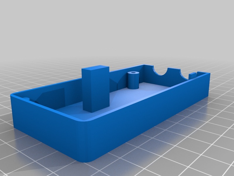
Basically this is a work in progress to test either 2801 or 2811 pixels and identify which pixel is malfunctioning. The problem is usually one of them, the faulty one or the preceding one when one goes bad. This box uses needles that pierce the jacket of the pixel wire to tap into the data signal. It's designed to be able to tap ground, data, and clock. A 9V battery powers it, but you can use a lipo or other power source depending on what you have and the voltage of your pixels. Since this box supplies its own power, you only rely on the data signal wires. So you can test both 5V and 12V pixels once it's set up. I'm using a slide switch for powering the box On/Off and a three-position DPDT micro switch to choose between 2801 and 2811 pixels. The switch will allow me to move the third pin to have nothing on it or clock only when it's 2801, ensuring that the voltage wire is not tapped into in a 2811 pixel. A wiring diagram has been uploaded to show how I wired everything up. When inserting the pins, you should grasp them with needle-nose pliers and press them into the holes. The point of the pin should go through the box, into the channel outside of the box, and be even with the end of the outside edge. See an image in the files section illustrating where the pins should extend to. I recommend having the middle, data, pin protrude a little more, allowing you to get into the jacket of the data wire first and help line everything else up. The wires to the pins just wrap around a screw and get screwed down onto the pins as shown in the photo. The pins were purchased from Wal-Mart and can be seen in the photo. The holes and channels were created using those pin widths. A 1/4" or 6mm screw length is recommended, allowing you to screw down all the way. I used a 3/8" screw instead, which didn't quite fit. You should pay close attention to what you're doing since you are the only one with your pixels in front of you and only you can know the wiring order. I am assembling this using my own pixels, currently Pixabulbs, Square, and Bullet Nodes. You have to be careful and attentive when working on this project. The switches I used are Radio Shack part 2750401 and Radio Shack part 2750620. Update 11/20/2018: I will upload a second version of the box that uses a SPDT On/Off switch, which is smaller and only powers the pixel type you're testing instead of powering both pixels up with data going to one. The wiring for this new version has been uploaded as well. This version will use Radio Shack Part 2750325 and Part 2750620.
With this file you will be able to print Pixel Tester Box with your 3D printer. Click on the button and save the file on your computer to work, edit or customize your design. You can also find more 3D designs for printers on Pixel Tester Box.