Pi Camera Teleprompter
prusaprinters
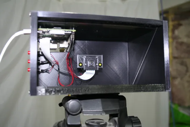
IntroductionThis model provides an effective, low-cost teleprompter for livestreaming and recording. Using a Raspberry Pi and Pi Camera (the cheap, non-HQ one provides great full-HD video in this application), your phone to display your script or talking points, and a small piece of glass or acrylic as the reflector, you are able to see your notes even as you make direct eye-contact with the camera. I use mine to stream the video from the prompter to OBS for use with live streams.You Will Need…A Raspberry Pi (if you can get one!). I used a Raspberry Pi 4, but a 3 should also work fine, and external access to the Ethernet and USB ports will still be no problem. A good power supply, too.A Raspberry Pi Camera: this project does not use the expensive HQ camera, but the cheap 5MP Raspberry Pi Camera v1.3 with the square board - you can get one for under £10, and it is more than capable of supplying a good quality, full HD stream. Make sure this is supplied with the appropriate ribbon cable.A piece of acrylic - this provides the 45° ‘mirror’ to reflect your script back at you, with the camera ‘looking’ through it. I found that plain clear cast acrylic worked perfectly well - half-mirrored is not necessary, and may reduce the image quality. The STLs are sized for a piece of acrylic 180mm x 140mm x 3mm.Printed parts: you will need to print one each of the STLs:RaspiPrompterV2_backplate.stl: the back plate also features the Pi Camera mounting pillar and a cutout to access ports on the Raspberry Pi. The mounting pillar also has holes for optional LEDs to ‘cue’ your eyes to look square at the camera.RaspiPrompterV2_baseplate.stl: the base plate features a slot for the acrylic, a hole and nut retainer for tripod mounting, and a raised lip to keep your smartphone from sliding out of the teleprompter.RaspiPrompterV2_camcover.stl: this camera cover ‘clamps’ the Pi Camera securely and accurately to the mounting pillar with M2 screws.RaspiPrompterV2_leftside.stl or RaspiPrompterV2_leftside_nobuttons.stl: features a slot to provide access to the Raspberry Pi's Ethernet and USB ports. While wifi works OK, I definitely prefer Ethernet - more bandwidth and less likelihood of interference. The ‘nobuttons’ version omits the three buttons, which I originally intended to use to start recording, pause, stop etc. Ultimately I found it much more convenient just to control all these things via OBS, so I don't use the buttons. They would be handy for ‘standalone’ recording though.RaspiPrompterV2_rightside.stl: just a plate for the right side.RaspiPrompterV2_topplate.stl: features a slot for the acrylic, which is held at the perfect 45° angle by the slots in the top and bottom plates. This also features mounting pillars for mounting the Raspberry Pi so that port access will be possible through the back and left side plates.M3 screws: the entire teleprompter is assembled using M3 screws. M3x12 self-tapping screws would be ideal, though ‘ordinary’ (non-self-tapping) M3 screws should work fine. I used non-self-tapping M3x16 because that's what I had on hand.M2 screws: the camera is held in place by four M2 screws running through the cam cover, through the holes on the camera board, through the holes on the backplate mounting pillar, with M2 nuts fixed behind the pillar. This makes for very secure and very accurate positioning of the camera module. You might get away with M2x10, but M2x12 or longer will be easier (and this is probably the fiddliest part of the assembly).A ¼" UNC nut (20 tpi). This is the ‘standard’ nut for a tripod mount - you might get away with an M6 nut, but the connection won't be secure and you could damage the threads on your tripod.Smartphone: You lay your smartphone in the ‘box’, resting on the base plate and held neatly by the lip. The screen of the smartphone is reflected in the acrylic pane for you to see/read, but the camera doesn't see it at all. There are some great free apps which will mirror the display, scroll your document etc - I use “Elegant Teleprompter” on Android which is free and works well.(Optional) Tripod: sure, you can put your camera on a stack of books, but working with a tripod is much nicer - easier positioning, control of angles, faster setup… doesn't have to be anything special, but a cheap tripod will make your life better.(Optional) LEDs: the two holes on the camera mounting pillar are to take 3mm LEDs in a standard 6mm-diameter LED holder. These are connected to GPIO pins on your Raspberry Pi (don't forget the appropriate current-limiting resistor). These are only there for ‘status’ notification and to provide a natural cue to your eyes as to where the camera is - you can't see it that easily in use. Don't make the mistake I did and use green LEDs - they were far too bright, and even with the brightness dialled way down with PWM were quite dazzling. Red LEDs are much better.(Optional) Buttons: I used cheap 6mm shaft diameter momentary buttons, connected to GPIOs on the Raspberry Pi. I've never actually used them, though, so I've included a version of the left-side panel which omits these buttonholes for tidiness.(Optional) Bluetooth remote/keyboard: this is a great convenience, allowing you to pause the teleprompter app, or increase/decrease scroll speed. If you get one, make sure it is supported by your smartphone/teleprompter app.Build InstructionsPrint all the parts. Only the back plate requires supports (for the widening on top of the camera mounting pillar). You will get the best results using black plastic - the reflection/look-through principle relies in it being much darker inside the box than outside. PLA works really well - you need good dimensional accuracy, especially for the camera mounts.Connect your ribbon cable (usually supplied with the camera). Make sure that the ribbon is the right way around - it has a directional orientation and will not work back-to-front.Mount the camera on the back plate mounting pillar - the camera cover fits over the camera module, so that only the lens is visible. Next run the M2 screws through the camera cover, the camera module and the mounting pillar. Holding the M2 nuts behind the mounting pillar, screw the screws into the nuts, just until it feels snug. Don't overtighten! I have fat fingers and had to hold the nuts in place with tweezers/needlenose pliers - YMMV.If you are using LEDs, mount them on the mounting pillar now.Mount the Raspberry Pi to the top plate with 4 M3 screws (ideally self-tapping M3x12 or similar). Be careful not to overtighten - the screws will handily ‘cut’ a thread into the plastic, but it is quite easy to strip this thread and ruin your part. Make sure the Raspberry Pi is oriented so the ports will line up with the slots in the back plate and left plate.If you are using buttons, install them on the left side plate.Fix the ¼" UNC nut into its recess in the base plate. If too tight, apply some heat (eg a soldering iron) and it will slide in. A little cyanoacrylate glue squirted into the bottom of the recess may help with permanence.Assemble the left side plate, top plate, base plate and back plate with M3 screws (ideally self-tapping M3x16 or similar). Again be careful not to overtighten. If you are using LEDs and/or buttons, it's easiest to screw the left side plate into the back plate, hook up to your GPIOs, and then attach the top and base plates.Set the assembly down on its left side plate. Slide the acrylic pane down along the slots in the top and base plates. It's a snug fit and may require encouragement, but be gentle - gentle taps from a soft mallet. You may find that a little spritz of silicone lubricant into the slots helps matters along. Keep going until it is flush with the edges of the top and base plates.Fix the right-side side plate to the top, base and back plates with M3 screws.All done! For the photos, I've illuminated the teleprompter from the front, so you can easily see the position of the camera and raspberry pi - but it will work best if you don't have a light shining into the front of the box. You want it to be much darker inside the box than outside, allowing the acrylic/glass to function as a one-way mirror.
With this file you will be able to print Pi Camera Teleprompter with your 3D printer. Click on the button and save the file on your computer to work, edit or customize your design. You can also find more 3D designs for printers on Pi Camera Teleprompter.