Phoniebox
prusaprinters
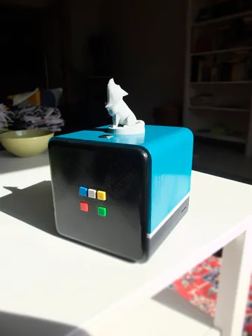
PhonieboxKids Music Box with RFID Reader and SpotifyI was searching for an open source alternative to a Kids Audio Box (e.g. Toniebox, Tigerbox, etc.) and found the Phoniebox as well as the Git for it.I went on to design a box that would fit all components (pi, powerbox, rfid reader, etc.) and found the tigerbox aesthetically pleasing. My box is larger to fit everything, around 14cm edgewise, but its still light enough to be lifted by my son who's not even two yet.The figurines are from thingiverse, remixed to include a slot which fits a RFID chip. Depending on the figurine put on top of the box a different playlist ist played, currently mostly kids audio books and a spotify music playlist.All in all a very cool project that i hope to expand when my son grows older.ElectronicsPhonieboxRaspberry Pi 3 - Model B+ - 1.4GHz Cortex-A53 with 1GB RAMPimoroni OnOff SHIM for Raspberry PiAdafruit I2S 3W Stereo Speaker Bonnet for Raspberry Pi - Mini KitAdafruit Perma-Proto Quarter-sized Breadboard PCB - 3 Pack!Colorful Square Tactile Button Switch Assortment - 15 packRugged Metal Pushbutton with Red LED Ring - 16mm Red MomentarySpeaker - 3" Diameter - 4 Ohm 3 WattUSB RFID ReaderPanel Mount Extension USB Cable - Micro B Male to Micro B FemaleAnker PowerCore 15000 ReduxM3 Screws (e.g. BangGood)RFID FigurinesRFID Button - 16mm (125kHz)PrintingThe files are a Work in Progress, as i'd like to include some of the changes i made in post-processing after finishing the box.Basically you need to print one of each of the files. I used Vertigo Grey for the bottom part and ReForm rPET for the rest.I printed everything at 0.28mm layer height, kept the bottom as-is and sanded, primed, painted and clearcoated the rest as needed.Edits2020_02_26: Uploaded the Source Blender File and a blank Front PlateAssemblyIntroductionThe Assembly can be separated into four modules:The Bottom Unit contains the Pi with Speaker Bonnet as well as space for the powerbankThe Front Unit with the Button SetupThe Back Unit containing the Speaker as well as a USB Port for charging the powerbankThe Top Unit containing the RFID Reader, Power Button including OnOff Shim and optionally two leds to show the status of the RFID ReaderStep 1: Back UnitThis is the simplest unit to assemble, as you just need to mount the speaker and the extension cable to the backplate.For the speaker i used some cables i had laying around, i think around 18 gauge. I soldered them to the speaker and put a jst connector on the other end.Step 2: Front UnitThe front contains the GPIO Buttons, that are mounted to the quarter sized breadboard.To solder the buttons i used a common ground for all buttons and soldered the data lines directly to the pi.If i would to this again, i would use connectors to keep it more modular.Button Layout:1 2 34 5Button --- Function -------- Pin 1 -------- Previous title -- GPIO20 2 -------- Pause/Play ------ GPIO X (Use a free pin, BUT NOT GPIO21) 3 -------- Next title ------ GPIO26 4 -------- Volume Down ----- GPIO19 5 -------- Volume Up ------- GPIO16Please check the pinout with your setup in mind. If there's a pin that's used for multiple functions, things will go wrong (e.g. GPIO21 is the default for Phoniebox' Pause/Play function, but has to be used by the speaker bonnet).Step 3: Top UnitOn the top theres a recessed area for the rfid figurines. Thats the spot on the inside of the top, where you should mount the RFID Reader (if its not working, you can always disassemble the reader and mount the coils on the top and the board somewhere at the side).The power button can be mounted in the hole, nothing special here. I used connectors to keep the design modular.Step 4: Bottom UnitOn the bottom there is room for the powerbank and mounting holes for the pi. As you can see in the picture, i directly mounted the speaker bonnet and soldered the OnOff Shim as well as the cables from the Front Buttons on this.Step 5: Software and Dry FitNow is a good time to connect everything together, setup the pi (i used Raspian Stretcher, because Buster was not supported at the time) and test, if everything is working.Here you will need to change the pins used by phoniebox to correct any conflicts (like with GPIO 21, that in default will be used by phoniebox as well as the speaker bonnet).At this step i found out that the top and bottom will fit nicely together, but give way if handled roughly (as is expected when used by a toddler). I bore some holes and inserted copper rods to stabilize the connection and counteract any lateral movement of the parts.Step 6: Assemble the PhonieboxIf the software is running and the dry fit went well, you will need 8 M3 screws for the final assembly.Step 6.1: Connect all the cables and electronicsStep 6.2: Fit the powerbank into the bottom compartement and connect it to the pi as well as to the extension on the back plate (depending on the cables used, it may be a very tight fit. I had to rotate the powerbank maybe 30° to fit my usb cables, because the connerctors where protruding quite a bit)Step 6.3: Connect top and bottom, no screws needed. I glued the white middle part on one side and inserted copper rods (with matching holes in the bottom) to prevent lateral movement).Step 6.4: Insert the front plate and use 4 screws to mount it to the top and bottom parts (these screws are hidden)Step 6.5: Insert the back plate and use the last 4 screws to mount it to the top and bottom parts (these screws will be visible from the back)
With this file you will be able to print Phoniebox with your 3D printer. Click on the button and save the file on your computer to work, edit or customize your design. You can also find more 3D designs for printers on Phoniebox.