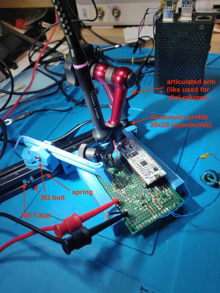
PCB testing fixture
thingiverse
###A Portable "3rd-hand" Style PCB and Testprobes Holder for Electronics Testing and Debugging. This setup has proven to be incredibly useful in holding oscilloscope probes firmly to PCBs during development, freeing up both hands for more complex tasks than just handling a probe. Some key details of the construction are: * The metal articulated arm was sourced from a low-cost dial gauge. The base was removed, and an M5 bolt is attached to the aluminum profile using an M5 T-nut. This arm provides excellent flexibility in holding scope probes at various angles while maintaining stability, even when a ground spring is attached for low-noise or high-speed measurements. * The aluminum profile used is a 20x20mm from Openbuilds, cut to approximately 20cm. * One side of the PCB is secured in place with an M3 bolt, while the other side is free to move along the rail, held in place by a ~50mm long spring that fits inside the profile and is secured by another T-nut. * The 3D printed second arm uses M3 bolts to hold both the base and the arm, making adjustments easy with hexagonal knobs by hand. * At the end of the arm, there's a 20mm long 1.35mm diameter spring-loaded "pogo-pin," soldered at the top side to a flexible silicone wire. The sharp tip and spring of the pogo-pin make it easy to apply enough pressure to hold onto a PCB testpoint or SMD pad. The design can be extended as needed by adding more profiles in an L-shape, which helps maintain flexibility with different board sizes. Adding one additional profile keeps the size flexibility, while two or three profiles allow for multiple arms/probes but limit the use of various board sizes.
With this file you will be able to print PCB testing fixture with your 3D printer. Click on the button and save the file on your computer to work, edit or customize your design. You can also find more 3D designs for printers on PCB testing fixture.
