PCB Drill
thingiverse
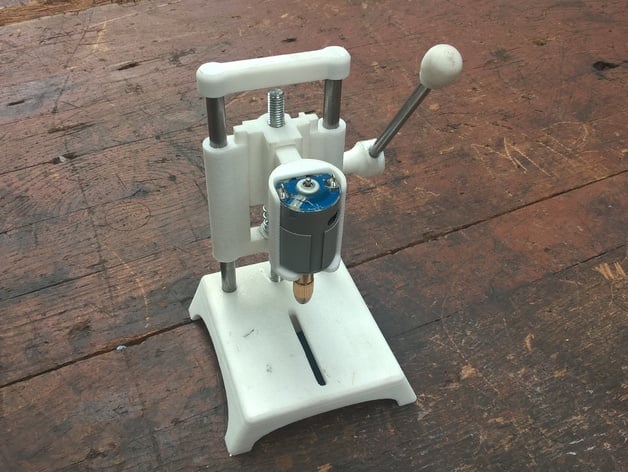
Hi guys, First off, I want to apologize for my English skills - if you notice any errors or things that don't make sense, please let me know so I can correct them. This is the PCB mini drill design. It's my first project, and I'm still learning as I go, so feel free to point out any mistakes or areas for improvement. I've included my SolidWorks 2014 files, which you're welcome to modify to suit your needs. The motor holder part is designed to be removable, so you can swap it out with a different type of motor if needed. To build the drill, you'll need the following hardware: * M8 x 13mm nut * M8 x 130mm threaded rod (1x) * 2 x 150mm rods (8mm in diameter) * 1 x 70mm rod (6mm in diameter) * 1 x 100mm rod (6mm in diameter) * Spring (1x) * Motor (39mm high, 29mm in diameter) You can find these motors in old printers or on eBay. Just search for "8Pcs 0.5-3mm Small Electric Drill Bit Collet Micro Twist Chuck Tool Kit CC". Here's how to assemble the drill: First, print all the necessary parts using a 30% honeycomb infill and supports only if needed. I recommend adding at least a 10mm brim to the body part. Next, get ready your metal parts and motor. You'll need to finish the body part with an 8mm drill bit to fit the rods tightly but freely. Attach the 8mm rods to the stand, insert the height_wheel into the back of the stand, and then try to screw it into the treated rod through the middle hole on the stand (no glue needed). Fit the 8mm nut to the body part, close it up, and glue it with the nut_cup using acetone. Insert the motor into the motor holder and then try to attach the drill head. Connect the motor holder to the slider part - this is designed to be a tight fit, so use sandpaper on both parts before assembly. Put the body onto the stand, string it up, and insert the slider with the motor. Now put the top_end part on. The next step is tricky: you need to insert the gear into the 6x70 metal rod. Drill a 6mm hole in the gear to make it fit tightly with the rod. First, insert the rod through one hole on the back of the body part, then slide the gear onto the rod, and finally push the rod into the opposite hole on the body (you can choose which side you want to have the handle - left or right). Complete the handle by inserting the handle_clutch onto the longer end of the 70mm rod, insert the 100mm rod into the clutch, and put on the handle_end part. Now you need to fix the gear to the 70mm rod. This is up to you (I might remake this part to make it easier to assemble in the future). Drill a 2.5mm hole through both the gear and the rod, then glue in a piece of 2.5mm welding wire. Otherwise, the gear may slide when force is applied to the handle. The drill should be complete now - all that's left is to solder some wires to the motor, connect it to a 12V (1.5A) power source, and try drilling some holes!
With this file you will be able to print PCB Drill with your 3D printer. Click on the button and save the file on your computer to work, edit or customize your design. You can also find more 3D designs for printers on PCB Drill.