 thingiverse
Parametric Hinge
Parametric Butt Hinge
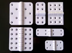
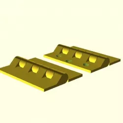
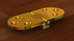
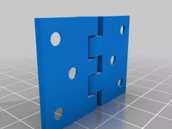
This is a parametric butt hinge designed in OpenSCAD, offering a wide range of parameters for customization. The hinge is designed to be printed in one step, but the individual leaves can be printed independently if desired. And in the case of applications that require an external pin, the default fused pin may be disabled, to leave a pin shaft ready to accept an external pin, during post printing assembly.
Note:
In the event that the Thingiverse Customizer is not working, which happens from time to time, you can still open and edit SCAD files directly in an SCAD editor, like OpenSCAD.
Experimental Version:
An experimental version of this model may be found here, https://www.thingiverse.com/thing:2351153
The experimental version includes additional features that are still being developed, or would otherwise over complicate the base model. I have made the experimental version available for those who would like to brave early access to some of the features that will possibly find there way into the base model, eventually. Please note, the experimental version is not updated as often as the base model, and may still include bugs and untested configurations.
Parameter Overview
Assembly Options
Male Leaf Enabled
Print the male leaf if true, otherwise omit it from the print.
Female Leaf Enabled
Print the female leaf if true, otherwise omit it from the print.
Leaf Fillet Enabled
Enable filleted leaf corners. Aside from aesthetic value, filleted corners can help with warping to a degree.
Pin Enabled
By default, the hinge is designed to be printed in one go, with a hinge pin fused to the female leaf. However, there may be applications where one may prefer to use an external pin. For instance, in the case where a metal pin is preferred for the sake of strength. In applications where an external pin is to be used, the pin may be omitted from the female leaf, by setting "Pin Enabled" to false.
Pin Auto Size Enabled
If true, this will set the pin diameter to the leaf gauge.
If false, the pin diameter may be specified by the "Pin Diameter" parameter.
Pin Shaft Counterbore Enabled
Cut a counterbore into the end caps of the knuckle joints if true.
While the pin shaft counterbore may be added even when the internal fused pin is enabled, the primary purpose of the pin shaft counterbore is to allow what ever external pin or bolt is being used in the case of an external pin, to be set flush with the top and bottom edges of the hinge, in the case where the internal pin is disabled, i.e. "Pin Enabled" is false.
Fasteners Enabled
Include fastener holes if true.
If false, leave the leaves free of fastener holes.
Knuckle Gusset Type
Select whether or not to use knuckle gussets, and if so what type. Knuckle gussets add strength to the transition between the knuckles and the leaves. The length of the knuckle gussets is equal to the fastener margin size, so that the gussets will never overlap any fastener holes.
There are four styles of knuckle gusset to choose from.
None: No knuckle gussets.
Linear: Straight edge gusset projected from a tangent on the knuckle down to the fastener margin on the leaf.
Circular: Basically a simple fillet, tangential to both the knuckle cylinder and the surface of the leaf.
Parabolic: A vertex form parabola, tangential to the knuckle cylinder, with its turning point tangential to the surface of the leaf at the fastener margin.
Throw Angle
The angle of the hinge joint. The hinge joint range is from +180 degrees fully closed, to -90 degrees fully opened. The default throw angle is 0 degrees, ie. opened flat.
This can be used either for assembly analysis, or in the case where one wishes to print the hinge standing vertically, it can be used to set a partially closed angle to keep the hinge stable during printing. For vertical printing, an angle of 120 degrees should keep the hinge stable during printing.
If you just want to print the hinge flat on the build plate, then keep the throw angle at 0 degrees for your printable model.
Flip Model
Rotate the model 180 degrees about the z-axis. This is useful for viewing the top and bottom pin shaft counterbore parameters.
Resolution
The geometric model resolution. Corresponds to the number of sides used to construct cylindrical parts of the model, like the knuckle joint segments, and the leaf fillets.
For example, a "Resolution" of 8, would specify cylindrical component elements to be constructed from 8 sides. a "Resolution" of 32 would result in 32 sided cylindrical component elements, and so forth.
For a smooth model, a "Resolution" of 64 and above is recommended. By default "Resolution" is set to 128.
Component Color
This is used purely to color the model in the Thingiverse Customizer. It should not affect the color of the model, printed from a color printer.
Hinge Parameters:
Hinge Width
The width in millimeters, of the entire hinge, from the outer edge of the left leaf, to the outer edge of the right leaf.
Leaf Height
The height in millimeters, of the hinge along the knuckle joint axis.
Leaf Gauge
Defines the thickness in millimeters, of the leaves and the radius of the knuckle joint.
Component Clearance
The inter-component gap in millimeters.
Recommended values range from 0.3mm for a tight fit, to 0.5mm for easy-er manipulation after printing. Clearance values of 0.3 or below can be challenging to print. I have succeeded in printing a few of these hinges with component clearances of 0.2mm and 0.25mm. However, quite often, sub 0.3mm clearance results in a locked up knuckle joint, where the leaves break before the hinge loosens up. A clearance of 0.4 or greater should release without to much trouble.
Note: The more knuckle segments there are, the greater the initial joint friction strait off the build plate. So for higher knuckle counts (7 or greater), component clearances of 0.4 or higher, may be required.
If the knuckle joint is not moving free at 0.4mm or higher, try re-printing slower at a higher resolution, in particular z resolution. Lower temperatures can help as well.
For PLA, a resolution of x=0.3, y=0.3, and z=0.15, at a speed of 6mm/s or less, with temperature 190 degrees C, seems to support a component clearances of 0.3mm to 0.4mm relatively well.
All of the sample STL files in the "Thing Files" section, are set to 0.3mm component clearance.
Knuckle Count
The number of knuckle segments in the knuckle joint.
This number should be an odd number.
For most applications, a knuckle count of 3 or 5 should suffice. However, higher knuckle counts can offer increases in strength relative to gauge size and hinge dimensions.
Pin Diameter
Manually specified pin diameter. This value is only used by the model, if "Pin Auto Size Enabled" is set to false.
If "Pin Auto Size Enabled" is true, then the pin diameter is automatically set to the leaf gauge size.
Pin Shaft Counterbore Parameters:
(Top or Bottom) Pin Shaft Counterbore Diameter
The diameter of the pin shaft counterbore. The counterbore is only added if "Pin Shaft Counterbore Enabled" is set to YES.
(Top or Bottom) Pin Shaft Counterbore Depth
The depth of the pin shaft counterbore cut. The counterbore is only added if "Pin Shaft Counterbore Enabled" is set to YES.
(Top or Bottom) Pin Shaft Counterbore Shape
The shape of the pin shaft counterbore hole. Currently circular, square and hexagonal are supported. In the case of square and hexagonal, the parameter "Pin Shaft Counterbore Diameter", refers to the diameter of a circle inscribed inside the square of hexagon.
For the square shaped counterbore, this means that the diameter of the counterbore is equal to the size of the sides of the square.
For the hexagon, the counterbore diameter is equal to the perpendicular distance between any two parallel sides of the hexagon.
The counterbore is only added if "Pin Shaft Counterbore Enabled" is set to YES.
Fastener Hole Parameters:
Fastener Head Type
Can be set to either counterbore for pan head machine screws, or countersunk for flat countersunk screws.
The chamfer angle for flat countersunk may be adjusted by varying the other fastener hole parameters. For instance, a thread diameter of 3mm (e.g. M3 machine screws), a head diameter of 9mm, and a countersink depth of 3mm, with give a chamfer angle of 45 degrees.
Counter Sink Depth
The depth below the surface of the leaves to sink the fastener heads.
For M3 machine screws 2.5 to 2.6 is usually enough.
If the fastener holes are not countersunk, then there will be mechanical interference between the fastener heads the the opposing leaves when the hinge is closed.
Fastener Thread Diameter
The diameter of the threaded portion of the fastener hole.
This can be made smaller than the fastener thread in order to support self tapping screws, or larger to give machine screws enough room to pass through.
Fastener Head Diameter
The diameter of the counter sunk head portion of the fastener hole.
Usually a good idea to make this diameter 0.5mm to 1.0mm larger than the actual fastener head diameter. For M3 machine screws, which typically have 6mm diameter pan heads, an "Fastener Head Diameter" of 7mm works well.
Fastener Count
The number of fastener holes per leaf. The total number of fastener holes in the entire hinge will be "2 x Fastener Count".
Fastener holes are arranged in one or two columns along the height of the hinge, as specified by "Fastener Column Count".
Fastener Column Count
Specify whether to arrange the fastener holes on a leaf, in one or two columns.
Fastener Margin
The distance from the circumference of the fastener head, to the edge of the leaf.
Values between 3mm and 5mm are recommended for small to medium gauge hinges.
Print Settings
Printer Brand:
RepRap
Printer:
RepRap Kossel
Resolution:
x = 0.3, y = 0.3, z = 0.15
Infill:
66% or more recommended.
Notes:
Print Speed, Resolution, and Temperature
To get a smooth moving hinge with a small component clearance (0.2 - 0.3), print slowly (4mm/s to 8mm/s), at a high resolution.
I have printed a few of these hinges in PLA at 190 degrees Celsius, with 0.2mm, 0.25mm, and 0.3 mm component clearances, using a 0.3mm nozzle, and a z resolution of 0.15.
Support
Supports are required to support the curved regions of the knuckle joint near the build plate.
For small gauge hinges, you could probably get way with no support at all. But for larger gauges of about 5mm and above, you will probably want to add a little support from at least 50 degrees for a nice neat curved finish.
No support is required for the internals of the knuckle joint segments, as long as reasonable component clearances of between 0.2mm to 0.3mm are used.
Build Plate Adhesion
If you have a heated build plate, then you should get away with a brim or a skirt.
If you are printing on an un-heated build plate, you may experience warping, in which case a raft should help, at the expense of a poorer quality finish on the bottom surface.
Post-Printing
For component clearances less than 0.4, the knuckle joints can be quite tough to free up. There is also a risk of the leaves breaking if you try to free up the knuckle joints with too much force.
For simple hinges with 3 to 5 knuckle joints, and a component clearance of 0.4mm or more, you may find that the hinge moves fairly freely strait off the build plate.
If the hinge is locked up after printing, which will most certainly be the case for component clearances of 0.3mm or less, there is something you can do to ease the process of loosening up the knuckle joint. What I find works fairly well is to soften the hinge in hot water for about 30 seconds, to a minute, and then very quickly take the hinge out of the hot water and rapidly try to move the knuckle joint. Because the hinge will be soft after removing from the hot water, care needs to be taken not to let the leaves of knuckle joint bend. If it looks like any part of the hinge is bending, put it back in the hot water and try again in 30 seconds to a minute, until the knuckle joint begins to loosen up.
I have never measured the temperature of the water. But for hinges printed using PLA, I find hot water from the bathroom tap seems to do the trick. The hot water in the case of my bathroom tap is just too hot for sustained contact with my hand, but cool enough that I can quickly reach in and remove the submerged hinge without being seriously burned.
If you are printing in ABS, you will need significantly hotter water, perhaps close to boiling, if not hotter. In which case, gloves and great care will be required in order to prevent injury.
How I Designed This
OpenSCAD
Fusion 360 animation, showing the throw range of the hinge.
Direct link to the original creator's page
Also Available On
More from rohingosl
Similar Models


Model Specifications
Frequently Asked Questions
How do I download Parametric Hinge?
Click the "View on thingiverse" button above to visit the original model page on thingiverse. You can download the STL file directly from the creator's page for free.
What 3D printer can I use for this model?
This STL file is compatible with most FDM 3D printers (Creality Ender 3, Prusa MK3S+, Bambu Lab, etc.) and resin printers (Elegoo, Anycubic). Check the original page for recommended print settings and materials.
Is this 3D model free to download?
Yes, this model is available as a free download on thingiverse. Some creators accept tips or donations.
Can I modify this STL file?
Most STL files can be modified using free software like Blender, TinkerCAD, or Meshmixer. Check the license on the original thingiverse page to see if modifications are permitted by the creator.