Pan & Tilt w/NEMA17 Steppers
thingiverse
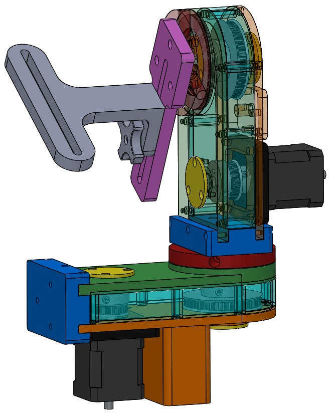
Latest update: 05AUG2019 Work in progress! This is a Pan and Tilt mechanism driven with NEMA17 stepper motors. This design was inspired by: https://www.thingiverse.com/thing:1396552 The belts (printed in NinjaFlex) are from this customizable source: https://www.thingiverse.com/thing:2682637 The pulleys were generated by this source: https://www.thingiverse.com/thing:2136539 I modified the pulleys to add cavities for screws and nuts and extended the hubs. I actually redesigned all parts to some degree, and made quite a few modifications including using heat set threaded inserts in many places, added bearing and belt covers, redesigned to make all printed parts more print-friendly (although the originals aren't too bad in that regard). I added a motor shock mount printed in NinjaTek Cheetah TPU (harder than NinjaFlex) and I changed the toothed pulleys to 18-tooth and 36-tooth, sized to fit a 3D printed T5 size timing belt 5mm wide with 62 teeth (may end up using 61 teeth). I printed the belt in regular NinjaFlex TPU. The 18-tooth pulley acts as a shaft coupler between the stepper motor and the 8mm diameter pulley axle. The 18-tooth pulley .STL file is for a 1/4 inch motor shaft, because I happened to have some NEMA17s with that size shaft. I have added an 18-tooth pulley for a NEMA17 stepper with a 5mm shaft. The metal pulley shafts are 8mm diameter steel or aluminum, however, these could be made from HDPE or other strong plastic. 3D printing these shafts is not recommended. One is 55.5mm long and the other is 20mm long. These lengths result in a 0.5mm end play clearance. I cut them on a lathe. The KnobCaptiveNut.STL part needs to be paused at 6.2mm height during 3D printing to install a 1/4-20 Jam Nut (not a regular size nut) into the part. Coat the top side of the nut with PVA glue (like Elmer's) before the print is resumed, so the plastic sticks to it. Chase the threads with a 1/4-20 tap after printing in case any glue ran into the threads. I print with a 0.4mm first layer and 0.2mm subsequent layers, so I need to pause at layer 30. If you print ALL layers at 0.2mm you would need to pause at layer 31 to add the nut. CameraBracket.STL part is used to adjust the fore and aft camera center of balance to line up with the tilt axle. The slot in the ArmAdapter.STL part allows up and down camera center of gravity adjustment relative to the tilt axle. Adjust both positions for best gravity centers to eliminate any floppy action. Hole sizes for the heat set inserts work on my prototype, but they could be shaped and resized per the manufacturer's specs for a better fit. Could be modified easily to accommodate either NEMA17 and NEMA23 motors. I may do that eventually. Ultra-quick video demo of input: https://youtu.be/GrmbCn-RxYA ***** (Oldest Update): Have uploaded a bill of materials file for the mechanical parts, excluding the Arduino controller parts, and the electronics housing parts that have yet to be designed. The BOM may (or may not) have errors. Screws, nuts, bolts, 8mm metal pulley shafts not yet illustrated here. ***** (Controller Parts): A BOM has yet to be created. 1 - Arduino Pro Micro 2 - A4988 Stepper Motor Drivers 1 - 8-bit I2C Serial Port Adapter 1 - 4x4 Matrix Keypad 1 - 20x4 LCD Display with I2C Adapter 1 - Power Supply, 120AC to 12VDC, 3A 1 - Power Converter, 12VDC to 5VDC 1 - Buzzer, 5VDC Misc. Wires, Connectors, etc. Housing and Cover Heat-set threaded inserts ***** (Original Post): This is a Pan and Tilt mechanism driven with NEMA17 stepper motors. This design was inspired by: https://www.thingiverse.com/thing:1396552
With this file you will be able to print Pan & Tilt w/NEMA17 Steppers with your 3D printer. Click on the button and save the file on your computer to work, edit or customize your design. You can also find more 3D designs for printers on Pan & Tilt w/NEMA17 Steppers.