 thingiverse
PALZero
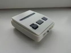
With plenty of love shown for the North American SNES for raspberry pi cases and the more aesthetically appealing (imo) PAL version being left behind, I decided to model one to suit a Pi-zero with working buttons and front facing USB ports.
It's a very easy print but requires some soldering for the USB ports and network card to work, I have written a draft guide for this but made a mistake with the GPIO wiring for the buttons. I aim to update this before Christmas 2016. I have uploaded all the images anyway in the hopes that you can see the general idea and make the corrections as you go. Otherwise simply leaving the buttons disconnected will work for the time being.
My XYZ orientation screws up the STL export so you will need to re-orientate the parts before slicing.
Supports are required for the top & bottom shell and I recommend removing any supports under the rear vent if your slicer supports it.
Print Settings
Printer Brand:
Printrbot
Printer:
Simple Black
Rafts:
No
Supports:
Yes
Resolution:
0.1mm
Infill:
40%
Notes:
BOM can be viewed using the link below.
https://docs.google.com/spreadsheets/d/1F_ArzNiFwMW9JimI16obwYbLgVDuH2v6bz6ATh1kTYQ/pubhtml?gid=0&single=true
Custom Section
All the parts are printed and cleaned up.
Most of the major components gathered.
The HDMI adapter needs to have the plastic casing removed, pretty easy with a hobby knife.
USB wires prepped for the front facing ports, about 100mm long is plenty.
Wire up and solder the female usb ports, use the orientation of the ports on the USB hub as wiring reference.
Repeat for the other USB port.
The USB port on the far end needs to be removed to allow for clearance needed for the power button switch terminals, the other ports aren’t needed either since I am wiring directly to the PCB but they’re not in the way so they can stay.
First front facing port soldered on, try to avoid this much exposed wires if possible. Place the new USB port flat on the table the same way up as the existing ports and make sure the wires match the USB pins on the PCB.
Second one soldiered on.
Second one soldiered on.
Wiring up the power switch, I used a small LED and battery to test which terminals to use. About 100mm of wire is enough.
Heat sink on both wires and then connected to the ground wire of the power USB port, I added some glue to the wires to keep them from shorting since my soldering caused the insulation to burn a bit.
Soldier about 40-50mm of wire onto the momentary switch and then add heatsink. I later found that these terminals were a bit too long and made for a very tight fit when putting the case together, It would be worth trimming these down to 2-3mm at most. Then add heatshrink
Here’s my wiring diagram, I used the following source to work this out. If my wiring diagram doesn’t make sense it should seem pretty basic after reading the following. https://www.cl.cam.ac.uk/projects/raspberrypi/tutorials/robot/buttons_and_switches/
1KΩ resistor trimmed short and soldiered in with a second wire soldiered on the switch side for the 10KΩ resistor.
Red heat shrink over the 1KΩ resistor and then soldier in the 10KΩ resistor. I used black heat shrink on the 10KΩ and made a note of it so I don’t get them mixed up.
The black wire is soldiered onto the switch for ground, the red wire is bundled up neatly with clear heat shrink. Repeat for the other switch.
Just lebeling the wires so I remember which resisitor is which.
The LED needs a 270Ω resistor wired to the 5v wire and then covered in heat shrink. I think It would be better to use a 3.3V LED to put less load on the PiZero but this is what I had on hand so it’ll do.
LED all done.
The power switch can be fed through the top of the switch mount and secured in place with glue after connecting it to the ground wire on the power supply USB cable.
Just a dab of epoxy to hold it in place.
The excess PCB on these USB/LAN hubs needs to be snipped off for it to fit in the enclosure properly. Don't worry, there's no magic stored here.
About 2mm or so trimmed off is enough.
The USB/LAN hub can be snapped in place, a couple drops of glue underneath wouldn’t hurt although it should already be a pretty tight fit.
Tucks the wires in and seat the USB ports in their slots.
The flared ends of the USB ports should sit in the retainer slots, this will stop them pulling out or pushing in when using them.
The nut and washer can be removed from the LED, these won’t be needed.
Everything should fit nice and snug in the slots before adding the clamp.
Clamp added and tightened. There should be no pressure in the middle of the USB ports, only on the corners. Most of the pressure will be on the LED as this will be a pretty tight fit, take a little material out of the clamp bracket around the LED if it’s too tight.
Trim the LED wires to length, about 75mm will do.
I used this image as reference for the GPIO pin locations along with my wiring diagram above. I am using the newer version of the PiZero but the GPIO pins are still the same.
LED wires are soldered to the PiZero on the 5v and the GPIO pin, I have routed them up through the bottom to keep the top from getting cluttered
Make sure these wires are snug against the PCB with as little exposed wire as possible.
The first button soldered in.
Second button soldered in.
I left a bit too much wire on this one which made it hard to fit everything in.
The buttons can then be screwed into the button mount.
Buttons in and ready for the button caps.
Button caps added, I added a drop of glue to the top of the buttons to keep them from rattling around.
The faux cartridge slot can be glued in place from the inside.
Test fit of the buttons, You can see my case is a bit rough on the inside from the printed supports.
Happy with the fit-up, I glued it in place.
Added the HDMI adapter and placed the power cable in it’s slot, It was a bit too tight so I used a craft knife to make a tiny bit more room before gluing it in place. The SD card can be prepared with RetroPie now, everything needed for this can be found here. https://github.com/retropie/retropie-setup/wiki/First-Installation
Installed SD card and case assembled
Assembly all done, time to program the buttons and LED. Guide for this will be uploaded soon.
Direct link to the original creator's page
Also Available On
More from ajcraig
Similar Models
 thingiverse
 thingiverse
 thingiverse
 myminifactory
 thingiverse
 thingiverse
 cults3d
 thingiverse
Model Specifications
Frequently Asked Questions
How do I download PALZero?
Click the "View on thingiverse" button above to visit the original model page on thingiverse. You can download the STL file directly from the creator's page for free.
What 3D printer can I use for this model?
This STL file is compatible with most FDM 3D printers (Creality Ender 3, Prusa MK3S+, Bambu Lab, etc.) and resin printers (Elegoo, Anycubic). Check the original page for recommended print settings and materials.
Is this 3D model free to download?
Yes, this model is available as a free download on thingiverse. Some creators accept tips or donations.
Can I modify this STL file?
Most STL files can be modified using free software like Blender, TinkerCAD, or Meshmixer. Check the license on the original thingiverse page to see if modifications are permitted by the creator.