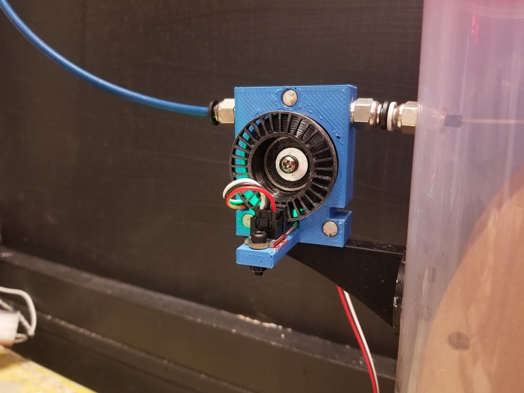
Optical Filament Runout Sensor
thingiverse
After trying rwmechs design. There were a number of changes i wanted. 1. The rubber band technique for friction was not working at all for me. 2. The wheel design did not put the bearing support over where the filament friction was 3. The sensor he used was not as common today 4. The bearing capture and riding surfaces did not work well to center and support the bearing causing the wheel to wobble 5. Filament loaded was a pain as the filament was not supported well passing through the device So the major change was to use orings as the friction for the filament. The filament rides on top of 2 orings that are next to each other providing a perfect v groove for the filament to run in. Minimal pressure and maximum friction. AND as a bonus, the filament loads perfectly as the v groove created by the 2 orings keeps the filament perfectly centered to capture the exit hole when loading. Ive included the freecad file, and step What you will need. 1 Optical sensor. I used from amazon ...5 Pack Optical Endstop with 1M Cable Optical Switch Sensor Photoelectric Light Control Optical Limit Switch Module for 3D Printer Brand: R REIFENG 1 M608 Bearing . Note. I removed the plastic bearing covers, cleaned out the thick grease. Added a few drop of motor oil, and reinstalled the plastic bearing covers. This dramatically cuts down on the bearing friction drag on the filament wheel. 1 M3 screw and washer to capture the bearing 1 M3 screw and nut to hold the sensor onto the case 6 magnets. 6x3mm 2 straight bowden m10 fittings 2 orings. R-15 O-Ring (ID: 22 mm, CS: 2.5 mm, OD: 27 mm). Video of it in operation here. https://youtu.be/cyISnw5r-1c I printed my cover in transparent so I could see the LED lashing.
With this file you will be able to print Optical Filament Runout Sensor with your 3D printer. Click on the button and save the file on your computer to work, edit or customize your design. You can also find more 3D designs for printers on Optical Filament Runout Sensor.
