Numbered drill guide - Customizable OpenSCAD
prusaprinters
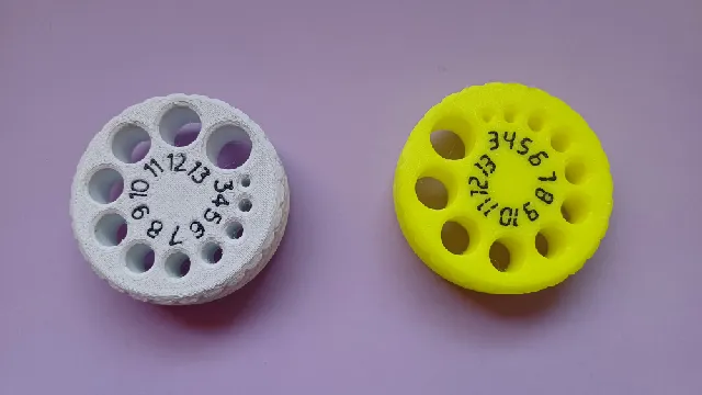
I pretty much liked squinn's drill guide and dust catcher, but I missed it having the drill diameters for easier, faster reference. So I made an OpenSCAD thingie, and here I'm including some STL (and even a SVG) so you don't need to generate your own —but I also added the OpenSCAD file, so you can make your own with the size and font you like most. “Drilling” the numbersThe number models simply is added as a negative volume/modifier/mesh to squinn's drill_guide.stl file. The number models include a non-printable “fillet” (a thin circle) to help in positioning; just put the numbers object at the same coordinates as drill_guide.stl, or (if you're using object coordinates, not world coordinates) at 0,0. Done.Then you have two main options: either print it “as is” and maybe color the numbers with a Sharpie or similar, or print in multicolor/multipart (with or without a MMU/AMS/other system). If you don't have it, you can either use the PoP (Print-on-Print) technique, or the “virtual tool” method, which works as a MMU/etc., only that the color changes are done manually.Since the numbers will be thin and a flimsy print, I suggest you use the virtual tool/MMU/etc. and a purge tower. In case you don't know, the Print-on-Print means printing first the numbers, removing the skirt and purge line, change filament and then printing on top of them the main guide part. You can set both models together in the slicer, making sure that they fit OK, and take advantage of the “hide model” feature (in PrusaSlicer, the eye at the right of each model's name in the list), sending one or another to GCode/print. The “virtual tool” method (or “poor man's MMU”) means making a setup in the slicer with several extruders and a single head, and adding the M601 color change gcode (and some others for flavour) at the “tool change gcode” box. There are many different implementations, and many tweaks to be made depending on your preferences; I won't go any deeper on that (at least for now). Anyway, you can find an example of “virtual tool” for the Mini, which I used for one of the pictured prints.Whenever you prepare files for PoP, it's better that the negative modifiers are slightly bigger and taller than the inserts, to avoid smudging. This means setting an offset to the texts of about 0.1-0.15 (relative to that of the inserts) and 0.5/0.6 height; you definitely shouldn't make the inserts taller than 0.4mm (about two layers at usual settings of 0.2 or 0.15 layer height). That's why the PoP folders have two sets of numbers: the thicker and taller are those to be used as negative volumes, while the thinner and shorter are the inserts. You can tell them apart by the _h?? and _t?? parts in the filenames.Why the SVG? And what are those Hershey fonts??I'll start answering the second question. In short, Hershey fonts are something very different to OpenType, TrueType, etc., fonts; while TrueType &so are “polygon” fonts (they're drawn with filled polygons), Hershey fonts are "stroke" fonts, like manual handwriting with a ballpoint pen. This means that they are very well suited for CNC machines (like, in this case, a 3D printer). You can set them to be, say, one or two extrusions wide, and you'll have a nicely drawn font; this solves some problems with gap filling and/or too thin parts of a glyph, which then are not printed.Implementing them in OpenSCAD is… well, complicated. (In my case, still experimental and prone to exploding.) But Inkscape supports out-of-the-box a wide range of Hershey fonts, and PrusaSlicer has now a wonderful support for SVGs. So you can use the included SVG as a reference for positioning the numbers, using another Hershey set in Inkscape, and then adding it to PrusaSlicer. That's what the included SVG is for.Doing your own numbersMaking your own template is very easy with the OpenSCAD file —even if you've never used the OpenSCAD customizer before. Just check the enclosed PDF “Using OpenSCAD customizer” and you're ready to go.When working with fonts, there are two main problems you may encounter. One is “improper” installation of the font; this is covered in the PDF. The other is the font resulting in some “impossible” geometry, which in short happens when a point is shared between two or more faces with opposite normals. In other words, you'll know when OpenSCAD throws an error. It has an easy fix: just set the value of the “Text offset” parameter to something different than 0 (0.1 or even less works wonders) and you'll be able to render it normally.
With this file you will be able to print Numbered drill guide - Customizable OpenSCAD with your 3D printer. Click on the button and save the file on your computer to work, edit or customize your design. You can also find more 3D designs for printers on Numbered drill guide - Customizable OpenSCAD.
