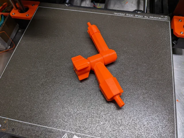
"Noga" Style Arm Indicator Holder - Jointed Single Action Locking Holder
prusaprinters
This jointed holder arm has the property that loosening the tightening knob loosens all three joints - the rotating middle joint, and the two ball joints. Conversely, tightening the knob tightens all three joints at the same time, making ti very convenient to set a position and then lock it into place.Here is a video which explains how the commercial version works : I created my print as a design exercise, and to see if I could get a 3D printed version to work. My design does in fact work, although not nearly as well as the metal versions. Still, I thought others might find some use for it (or at least for the design concepts). AssemblyIn addition to the printed parts, you will need a hex head M5 X 60 machine screw and matching hex nut.Note that there are two “arms” - one large (BallJoint06B- files) and one small BallJoint06- files). They both go together in essentially the same way, but the parts are not identical so be sure to keep them separate.The small arm is assembled as follows :Insert the ball into the socket in one half of the armInsert the push rod into the same half Note orientation of the push rod:The angled face goes at the “hole” endThe flat side of the angled face should face the “hole”With the ball and push rod in place, add the second half of the armWhile holding the two halves of the arm together, verify that the push rod is properly positioned by viewing it though the axle holeAdd the sleeve LOOSELY onto the end of the arms to hold them together (hard to get off if you make a mistake). Note the SLOT in the sleeve must line up with the matching slot in the end of the arm,Insert M5 screw into the small cylindrical with the hex recess, so that the hex head fits into the recessInsert the screw and pusher into the axle hole so that the angle on the face of the pusher matches the angled face on the push rodInsert the second pusher onto the screw and into the axle hole, again so that the angled faces match up.Add the sleeve LOOSELY onto the end of the arms to hold them togetherThe large arm is assembled in much the same way.Insert the hex nut goes into the hex recess in the knob, and push it down to as far as it will go.With both arms assembled (sleeves still “loose”), join the two arms together using the M5 screw, and screw the knob onto the screw to complete the assembly (but don't tighten it fully yet).Verify that all the parts are assembled correctly. If so, push the sleeves fully onto the ends of the arms (I do this by rotating the ball stem out of the way into the slot, and then pushing the arm end down onto a flat surface. The sleeves are a tight fit, but should be essentially flush with the end of the arm when fully seated.At this point you should be able to rotate the two arms, and move the ball joints fairly freely. You can now tighten the knob to lock everything into position. Experiment with tightening the knob so that the joints lock, but the knob is not so tight as to break things. My print requires one full turn of the knob for a good lock. Print InstructionsPrint the parts in PETG using the gcode or 3mf files provided; in general :3 perimeters0% infillexcept 15% rectilinear infill for the knob.See the photos for recommended part orientation.CADThe OnShape 3D CAD files for this are here :https://cad.onshape.com/documents/daa24b8324a91cb603797f4c/w/ef898285ad0fa691a7d23691/e/798b25404bcab385c5a839a4
With this file you will be able to print "Noga" Style Arm Indicator Holder - Jointed Single Action Locking Holder with your 3D printer. Click on the button and save the file on your computer to work, edit or customize your design. You can also find more 3D designs for printers on "Noga" Style Arm Indicator Holder - Jointed Single Action Locking Holder.
