Mousetrap car
prusaprinters
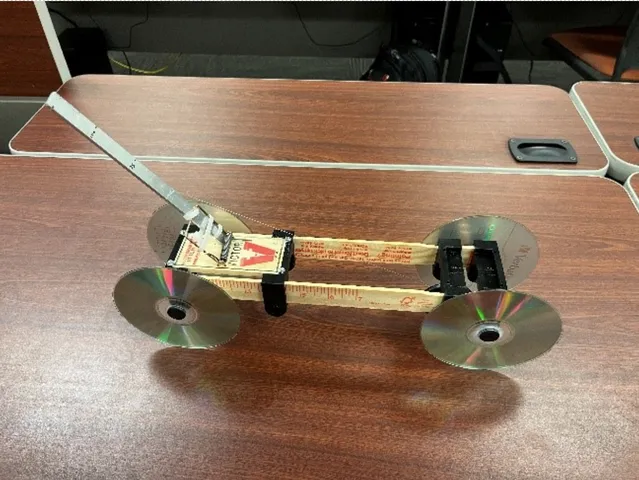
Before designing the car, each team member watched a video discussing the science behind mousetrap cars by Mark Rober. Rober is a former NASA and Apple engineer turned YouTuber. He does a wonderful job highlighting the fundamentals in this video. Although a design from his video was not chosen, many of the specific ideas used started here. The main goals going into the design phase were to reduce friction and keep the car as light as possible. CDs from the kit provided were used for the wheels and, of course, the mousetrap from the kit was used for power. Bearings were used to reduce friction. However, bearings that match the axles provided in the parts kit could not be easily sourced. So, ¼ inch steel rod was selected for the axle size because bearings with an inner diameter of ¼ inch are cheap and easy to find. It was also theorized that it would be easier to wrap the driveline around a thicker axle. The next step was to purchase materials. While shopping at the local hardware store for round stock for the axles, some additional materials were purchased that might be useful. Paint stir sticks were picked because they were very cheap, very lightweight, and seemed to be around the same length as some of the cars seen in the video. Mason line was also chosen for the driveline because it is lightweight, easy to handle, and does not stretch very much. ½ inch by 1/8 inch aluminum flat stock was also purchased from the hardware store for its high strength to weight ratio. Inexpensive bearings were found and ordered from an online retailer for cost-saving purposes. The rest of the parts used to assemble these items would be designed and 3D printed in the design phase. Based on the information provided by Rober’s video and past teams in this course, the goal was to design a car that would be powered along the 140-foot hallway. To achieve this, it was designed to not waste energy by avoiding spinning the wheels or traveling at speeds high enough to make air resistance a factor. Given the materials already collected, the total length of the car would be around 12 inches. So, the lever arm attached to the mousetrap would need to be shorter than that, around 10 inches. Some quick calculations lead to the conclusion that this size arm could not power the ¼ inch axle for 140 feet. It was decided that a pulley system with a secondary driveline would be used to decrease torque at the wheels. This solution made the design process more complex. To help with this added complexity, an Excel table was created to assist with the calculations of arm length and pulley size during the design phase. This is shown in Table 1. Also, at this time the team was operating under the assumption that the mousetrap spring in the factory configuration would be able to produce enough power to move the car the entire length of the hallway; this assumption was incorrect.Table 1: Pulley and Lever Arm CalculatorMousetrap Car Calculations Fixed Var.Track (mm)CD (mm)Axle (mm)Pulley (mm)Lever Arm (mm)Lever Arm (mm)42672376.819.468142.1241356302Pulley Dia. (mm)42672376.819.46894.2455.6421333Track (mm)42143.6004376.819.468141.3300Fixed Var.Track (ft)CD Dia. (mm)Axle Dia. (mm)Pulley Dia. (mm)Lever Arm (mm)Lever Arm (mm)1401206.245.26246358151Pulley Dia. (mm)1401206.230227.8210667Track (mm)138.2664061206.245150DESIGN The design process started with a quick sketch of what the car would look like. A rough draft approved by the team is shown in Figure 1.Figure 1: Basic Design SketchThe next step was to create 3D models of the materials purchased and provided in the kit. This included the CD, mousetrap, bearing, paint stir stick, ¼ inch round stock, and ½ inch flat stock. Custom parts were then designed to bring everything together. Wheel hubs connected the CDs to the axles. They were designed to be glued onto the CDs and pressed onto the axle. The crossmember was designed with multiple functions in mind. Four identical crossmembers were used in the car even though all of the features were not needed in some areas. This was done to simplify the assembly of the car and the printing of the parts. They align the stir sticks that act as the frame and can be secured with a #4 set screw for alignment and rigidity. They also secure the mousetrap by clamping it down with #4 screws and washers near the four corners. Finally, the crossmembers house the axle bearings which are a press fit. A 45mm pulley was designed. This size was chosen because it was the biggest pulley that would fit under the crossmember and if there was a problem during assembly, it would be easier and faster to change the lever arm length. Lastly, the models were put together in an assembly shown in Figure 2. Figure 2: 3D Model Assembly (with labels)BUILD Before the team came together to build the car, a few pre-build tasks were completed. First, the bearings arrived covered in a tacky grease. They were soaked in penetrating oil to dissolve the grease and reduce friction. Meanwhile, the 3D parts were printed. Also, additional materials were purchased including #4 screws, glue, and Zip Ties for attaching the lever arm. While building this car, the team quickly learned the benefits and downfalls of this design, and certainly, mistakes were made. First, the stir sticks fit so well in the crossmembers, that it was determined that set screws were not needed (this would become a problem on the second trial run). The bearings, mousetrap, and wheel hubs also fit well and allowed for removal if needed. The pulley/axle design was a bit problematic. Nothing was keeping the axle from sliding out of the bearings. To solve this, glue was used to attach the axle to an inner bearing race. The aluminum flat stock was chosen for the lever arm because it is more rigid than the wood stir stick. Another problem arose when attaching the lever arm to the mousetrap. It was difficult to keep it from shifting at the connection point under load and because of the thickness of the metal and Zip Ties, the 180-degree arc of the mouse trap was decreased. Therefore, the arm was made longer than the length calculated by the Excel table so the car would still be powered for the length of the hallway. It was then discovered that the mason line was too thick for this application, and it did not spool well on the axles or the pulley. Luckily, there was fishing line available, so it was used instead. This design was to be hard to prepare because the lines were difficult to route. There is not a lot of room to work and the two lines were easily tangled together. Even though there were setbacks and design flaws, the car was ready for the initial test run.
With this file you will be able to print Mousetrap car with your 3D printer. Click on the button and save the file on your computer to work, edit or customize your design. You can also find more 3D designs for printers on Mousetrap car.