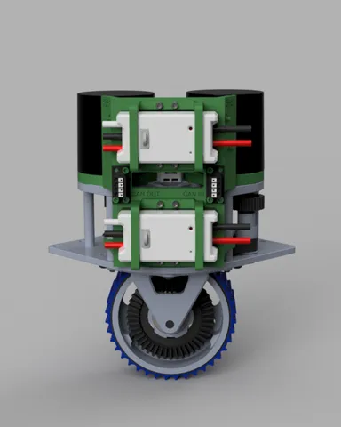
Motor Controller Mount for SDS MK4 Swerve Drive (FRC)
prusaprinters
Primarily for use in FIRST® Robotics Competition robots that use the Swerve Drive Specialities MK4 Swerve Module, this is an integrated motor controller and CAN bus connecter mount.Designed for FRC team 5881, the Tech Valley High School Dragons, this mount integrates 2 REV Robotics SPARK MAX motor controllers, and (4) CTRE CAN Connectors. Using the existing mounting and structure of the module it allows for a cleaner connection to your electrical and CAN busses while keeping the controllers near the motors.Needed Hardware:(18) #4-40 3/8" SHCS(18) #4-40 Nylock Nut(2) #10-32 3" SHCS (Replaces screws from Swerve Kit)(4) CTRE CAN Connectors(2) SPARK MAX Motor ControllersPrinted Parts:(1) Backing Plate(2) Motor Controller Mount ClipsPrint Settings:Material: PETG Recommended, PLA should be finePart Orientation:Mount “Front” face should be on the bedClip should be placed with the back of the screw holes on the bedSupports: Recommended for the clips. Optional for the mount plate, but suggested.Layer Height: 0.2mmAssembly:Follow the rendered images and mount your motor controllers and CAN connectors. CAN connectors will recess slightly into the main body and not all screw holes will be used. Pre-wire the CAN bus on the module using #4-40 screws and nylock nuts:Top SPARK MAX CAN connection to the external-facing “CAN IN” (right) side, and the 2nd connection to the “CAN IN” side inside connector.Bottom SPARK MAX CAN connection to the external-facing “CAN OUT” (left) side, and the 2nd connection to the “CAN OUT” side inside connector. Note the orientation of the CAN connectors on the inside of the module. Flipping 180deg is possible, but makes accessing the terminals harder once attached.(Note: It is recommended to put ferrule connectors on all CAN bus wires)When screwing in components the nuts should sink into the rear of the module with just enough friction to prevent them from falling out.To attach to the MK4 Swerve Assembly, remove the (2) #10-32 screws from the top rear of the module. These will pass through the spacers in the middle (gear) section. It helps if you loosen the bottom #10-32 screws a half turn or so.Take the spacers and feed them through the “clips” on the bottom rear of the mount. Push them up or down through the opening, do not attempt to push them in from the side and “snap” them in, you'll break the part. Leave room near the top arms to fit the top plate.Next begin positioning the module such that the top arms are over the holes for the removed #10-32 SHCS. At the same time, pull the two sets of motor wires through the hole in the mount to the front. Move the CAN wire from the CANCoder up and out of the way for now. Align and insert each #10-32 3" screw down from the top of the assembly, through the arms of the mount, through the top plate, through the spacers, and into the bottom plate. Once you get the first aligned, give it a few turns and start the second one.Next complete the CAN circuit by connecting the CAN wires from the CANCoder to the two CAN connectors on the inside of the mount.It is recommended you power and test the entire assembly (and set CAN IDs as needed) on a test bench before mounting the module to your chassis.
With this file you will be able to print Motor Controller Mount for SDS MK4 Swerve Drive (FRC) with your 3D printer. Click on the button and save the file on your computer to work, edit or customize your design. You can also find more 3D designs for printers on Motor Controller Mount for SDS MK4 Swerve Drive (FRC).
