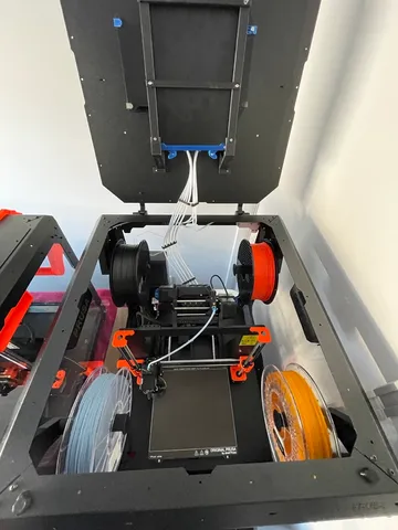
MMU3 Buffer + Prusa Enclosure Internal Lid Mount (Mod 1)
prusaprinters
I have recently found a few issues with this model, and have plans to redesign.Why ?What I found is that some of the filaments push back into the MMU after an unload. This causes filament to poke out into the path of the selector, causing a possible jam. I also do not like the way that the Finda wiring is bent too sharply to have great longevity.I am rethinking this whole thing. Considering now mounting the buffer internally behind the printer, and thinking to design a bracket attaching the buffer to the enclosure frame. This would, I think make loading of the buffer easier, and gravity will help to stop the push back mentioned.The last photo attached to this model shows the concept, taken from Fusion. The model is not yet tested, and i will post it separately when i am sure of it.I'll keep this model online for those who already made it. I'd be interested to hear of any folks who encountered the same issue I observed.Attention folks: This updated version now includes side and rear plates to cover the large (Left, right and rear) openings in the buffer. This prevents filament loops coming out that may tangle then the lid is closed. There remains enough space inside the buffer for up to 600 mm of length between the MMU and the Extruder, which should be plenty.Also included are stronger rear brackets, and some geometry changes to eliminate strain on the brackets, since I found on the earlier version that there was a strain related breakage a few days after initial installation. This version uses plastic modelled M3 threads for all of the screws. This mitigates against frequent assembly/disassembly of the kit. If you find yourself doing that, then you will need to add M3 nuts and slightly longer screws. There are also updated print instructions, I'm now suggesting 25% infill on the rear brackets for greater strength.=======Motivation behind this remix of the Prusa Original Buffer unit:I found that mounting of MMU3 Buffer inside Prusa Original Enclosure on the floor of the enclosure was unsatisfactory. The Buffer cannot fit to right of Printer (Mk4 / Mk3S ) due to interference with right Z axis. Also when the buffer is placed behind the printer there is a chance of interference with the Y axis (bed Plate).The remaining choice is to place the buffer outside of the enclosure, but this leads to very long runs of filament guide tubing, and no easy placement of the rolls of filament and the buffer. Hence this design, which keeps the buffer inside the enclosure whilst avoiding the above issues.My solution is to mount the buffer unit horizontally under the lid and to have filament rolls attached to each of the 4 corners of the enclosure, similar to the standard roll holder. The 5th Roll could mount outside the enclosure, inside a dryer unit for example.I consulted with Prusa Support on this proposal, based on the original prototype design, and they expressed concern that perhaps the bends in PTFE tubing would be a little tight, could lead to excess friction passing filament. I felt that there was only one way to find out, which is to build the thing, so herewith my design.In testing, I found it useful to use 2.5mm ID, 4mm OD tubing (instead of 3mm ID variety), to reduce the likelihood of kinks developing in the tubing that would impede free filament passage. This printables item includes the original Fusion 360 design archive (.f3d). I posted it here to allow easy remix of the design if you need it, and further improvements are welcome.Instructions:1. Print Parameters:- Filament Type PETG or PETG CF, colored Black to match the MMU and enclosure. You need the strength of PETG to hold the weight of the buffer unit, cassettes and brackets.- Print using MK4 or MK3S+ printer with Hardened steel Nozzle 0.4 mm, and Textured Plate.- Print inside the enclosure, or warping may occur.- Use standard Prusa Slicer profiles for printer and filament, but Increase Retraction and Lift and use dry filament (!)- Infill 25%.- Organic Supports on Build Plate will be needed for the 4 mounting brackets. Snug also works OK, and prints a little faster.I have not provided any pre-sliced files, because you will need to produce your own, to suit your printer and the filament you choose to use. I have also provided the original Fusion 360 source model for this project, so you have a leg up should you choose to make changes to the design.2. BOM:- Qty 4 x M3 x 6mm Black Hex Socket Screws for mounting brackets onto the lid- Qty 2 x M3 x 10 mm SS Socket or CSK screws for middle frame horizontal bar- Qty 4 x M3 x 12 mm CSK Screws for front and rear frame horizontal Bars.- Qty (you determine) of 2.5 mm ID x 4mm OD PTFE tubing.From other projects:- MMU3 Prusa Design (Cassette) Filament Buffer including the cassettes and front plate that mounts them. Mounting foot is not needed. Buffer clips are not needed .- Print additional 3 x Spool Holders, and you will need 2 x 6mm M3 socket screws for each to mount.- Print additional 3 x Filament guide brackets. You will need 5 x M3 x 6mm socket head screws and 2 x M3 Hex nuts to assemble and mount each bracket.- Hinged lid accessory for enclosure installed.3. Assembly Instructions:It's all pretty obvious to me, but for those needing guidance herewith some mansplained instructions.3.1 Action list:Preliminary steps:i). Print out of the needed parts. When completed, test the screws in the plastic threads, and if necessary, clean the threads of each threaded screw hole on brackets and frame parts, using an M3 tap. to ensure easy assembly later on.ii) Remove the hinged lid from the enclosure, and place it upside down on a large cardboard box or Lack Table.(a) Assemble the buffer main unit, using recycled plates and cassette holder plate.(b) mount the 3 x clip-on cover plates on left, right and rear of the buffer unt. Take care not to break off the clip tabs on top and bottom, which go into the holes on each corner of the plates. (I did!)(c ) assemble the support Frame consisting of 2x Vertical and middle horizontal sections using the 2 x CSK M3 x 10mm screws. (d) Attach the mounting brackets on the 4 corners of the frame and secure using the 4 x M3x12mm screws that go thru the frame and into the brackets. This assembly should incude the top and bottom horizontal bars an the sandwich. Positioning of the brackets: The “rear” brackets go on the handle end of the enclosure lid, the “front” brackets go on the hinge end of the enclosure lid. (see photo)(d)- Place the Buffer into position on the lid. Cassette opening towards the hinge.- Place Frame on top of the Buffer, and fit the buffer into the front and rear brackets with care.- Insert the buffer unit in between the two front brackets and below the frame.- Secure the brackets into position on the lid using 4 x M3 x 6mm screws inserted from below the Lid. I found this is easier if you poke a piece of filament thru the holes to help align them.(e Replace the lid with assembled buffer unit back onto the enclosure, and secure using the previously removed 4 x M3 x 6mm screws.(f) Place spool holders into position on each corner all facing front-back direction. Secure each using qty 2 x M3 x 12mm screws(g) Place 4 x tubing into the 4 x filament guide brackets. The right rear guide bracket will need to be installed in reverse orientation to have the tubing facing the right direction and feed to the Buffer along the shortest path.(h) determine optimal way for tubing to be routed to the filament buffer guided around the upper corners of the enclosure, secured using zip ties. Tubing should be just long enough to perform its task, not longer, as excessive length can cause a traffic problem inside the enclosure.(l) cut the tubing to length (with a little slack) at the position of the buffer unit in the lid. Insert tubing into each cassette, secure using Collet and Collet Clip. Organise the tubing as a group of 5, tidily using tubing clips provided as part of UltiMulti Project. Note: 1 x tubing should be fed thru the top of the enclosure lid, destined to be plugged into a dryer unit or an exterior roll holder.(m) Insert tubing into output side of each cassette, bind together using a tubing clip, and feed to the rear part of the MMU, secure using collets or Festo fittings.The cassette design has both input and output tubes angled toward each other, and so its tricker to organise them so they do not tangle and allow easy insertion and removal of each cassette. You can check out the photos to see what I'm talking about. Have fun to organise them in a way that works for you.(n) Cut tubing (leaving a little slack) to length, and insert into MMU rear adaptor, secure with collet. Note that the tubing must go right thru the fitting and 20 mm into the MMU body towards the filament drive until it will move no further. The length of the tubing between mounted cassettes and the MMU is pretty important to get right. If its too long the tubing can kink, and likewise if its too short. I found making it long initially, then trimming the 5 tubes as needed by trial and error (opening and closing the lid whilst inspecting from the side), worked for me.(o) Loading of the cassettes. I find this to be devilishly tricky to do, since I have only 2 hands, but needing 3 for the task. The filament needs to be loaded into the cassette, routed around to the output side then pushed thru to the MMU rear entry points, then pushed into the filament feeder chamber in the mmu, then a little further to reach the output side of the filament feeder chamber. Its complicated by an upward curve on the filament. There is some possibility that most of the time, you may be able to load filament by pushing from the cassette end, and then push the middle black button on the MMU. If somebody comes up with a viable technique, please let us all know !.Reference the photo to check correct assembly
With this file you will be able to print MMU3 Buffer + Prusa Enclosure Internal Lid Mount (Mod 1) with your 3D printer. Click on the button and save the file on your computer to work, edit or customize your design. You can also find more 3D designs for printers on MMU3 Buffer + Prusa Enclosure Internal Lid Mount (Mod 1).