MKS 1.4 Electronics Box
prusaprinters
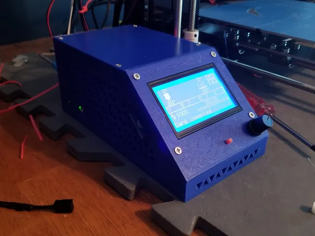
Electronics box for MKS v1.4 mainboard and 12864 LCD. The back plate has mounting holes for a 40x10mm cooling fan. I designed around a spare Noctua fan I had. All pieces are held together with M3 self tapping screws I got from Amazon. I have also included a test section of the triangle pattern. I used this to make sure my printer settings would be able to print the pattern with minimal problems. The ANET A8 wire length was designed around having the main board mounted half way up the frame. To get full Z travel I needed to extend most of the wires from the extruder assembly. I also printed and used the LCD spacer from mightynozzle to keep the two LCD boards in place but this may not be totally necessary https://www.thingiverse.com/thing:2813298 There are also two zip-tie points inside the case. Reset button may need to be sanded. Parts I used: MKS_Gen_V1.4 RepRapDiscount 128x64LCD Noctura 40x10mm fan M3 Self-Tapping Screws: 6mm x 4 8mm x 4 10mm x 2 16mm x 4 25mm x 4 extra wire Lots of cable ties Print Settings Printer: Anet A8 Rafts: No Supports: No Resolution: .2 Infill: 25% Cubic Subdivision Notes: All overhangs were designed to print with no supports. Post-Printing I found it easiest to first pre-tap the screw holes with the M3 screws before inserting the board. Place the 6mm screws in the board holes and slide the board in from the front. This is a lot easier than placing these tiny screws when the board is in the print. Screw in the 25mm screws until they just poke through the printed part Next place in the reset button then place the LCD. Tighten all 4 screws evenly for alignment. Screw in until they just go through the LCD. The encoder cap can now be placed back on but leave a gap so the push button can operate For my fan 16mm screws were needed With all parts now ready, rewire the main board. There are two mounts for cable ties. Tie the cables into two bundles, one on each side. This will make it easier to secure the back panel. Route these wire bundles into the two slots on the back plate and secure it with the 10mm screws. If you have a fan plug it in. Now connect the ribbon cables to the board and LCD. Fold the extra length over the board and place the LCD on the screw points. Tighten all screws evenly for proper fit. The top slides on from the side and is secured with the 8mm screws Category: 3D Printing
With this file you will be able to print MKS 1.4 Electronics Box with your 3D printer. Click on the button and save the file on your computer to work, edit or customize your design. You can also find more 3D designs for printers on MKS 1.4 Electronics Box.