MK3 Y Axis Linear Rail System remix
prusaprinters
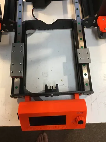
This a remix of the jfromel Y Axis Linear Rail and Belt System https://www.prusaprinters.org/cs/prints/23893-y-axis-linear-rail-and-belt-system It is a nice idea so I have made it. It works much better than the original MK3 Y axis system. Nevertheless, I was not completely satisfied because impossibility to adjust it completely. The movement was not smooth fully. The reason of it? Everybody knows: “No body is perfect!” This is valid for 3D printer parts too. Original carriage mounts fit tightly to the frog; carriages fit tightly to carriage mounts so there is not any clearance to adjust them. All part inaccuracies are transferred to the carriage balls without any possibility to solve it anyhow. Therefore, I have decided to do it a different way. I have removed carriage mounts and replaced them by simple spacer plates. There are no brims generating unwanted tensions and torsions in this case. I have made them from a 3mm hard aluminum plate. It could keep carriage surfaces parallel and should not be deformed by any unequal crew tightening or temperature I mean. Nevertheless, you can use the Spacer_plates.stl file and print them alternatively. Additionally, I have changed an assembly workflow to make it easier, more accurately and straight forward. The first two steps stay unchanged: Modify the frame as shown in the pictures so that the 45 degree angle of the frame is at 90 degrees to the front extrusions and spans the length of the extrusion (30mm) also make sure the top of the extrusion is at least .01mm taller than the frame so that the rail only contacts the extrusions. I used a coarse square file to modify the frame. Make sure that all the dust and metal filings are completely removed from the printer prior to proceeding. STL of the modified frame is included for reference. Modify the frog by adding additional mounting holes so that the carriages can mount securely to the frog. Jigs are in the temp parts 3mf file. Mount each jig with m3 screws/nuts. Use a 3mm drill bit for the additional holes (drill press is suggested). STL of the modified Frog is included for reference. Following steps are different. Photos attached could guide you. Use a piece of a 1.5mm diameter steel rod and put it through the most left screw holes in the front and rear frame plate. Align the left rail to the rod and fix it to frame in this position by screws. Repeat it on the right side. Rails should be parallel now. Measure rails distance at both outside rail screw positions. It should be identical. You should release the right rail a little bit and correct its position if necessary. You can use printed crossbars instead of the slide calliper alternatively. Set carriages to correct positions, put spacer plates on them and put the frog on the top of it. Insert screws to holes and fix everything together – do not tighten them fully yet. Try to shake the frog. It should be possible a little bit. There should not be any tension or blocks. You can increase frog screw holes up to 3.5 mm if necessary. Starting with left carriages slowly tighten each screw in a cross pattern such as top right, bottom left, bottom right, top left. Every time you tighten up a screw test that the rails are perfectly smooth. Do the same with the right carriage. It should work smoothly without any problem now. You can release the right rail and adjust its position if necessary. Mount the heat bed and do a Z axis calibration on the end of story. That is all. I am very satisfied by the result. The Y axis movement is smooth, quite and very precise. No Y crash occurs. Print instructionsUse a PETG, 0.2 layer and 100% infill Plates should be robust and heat resistant as much as possible.
With this file you will be able to print MK3 Y Axis Linear Rail System remix with your 3D printer. Click on the button and save the file on your computer to work, edit or customize your design. You can also find more 3D designs for printers on MK3 Y Axis Linear Rail System remix.