mini-tray
prusaprinters
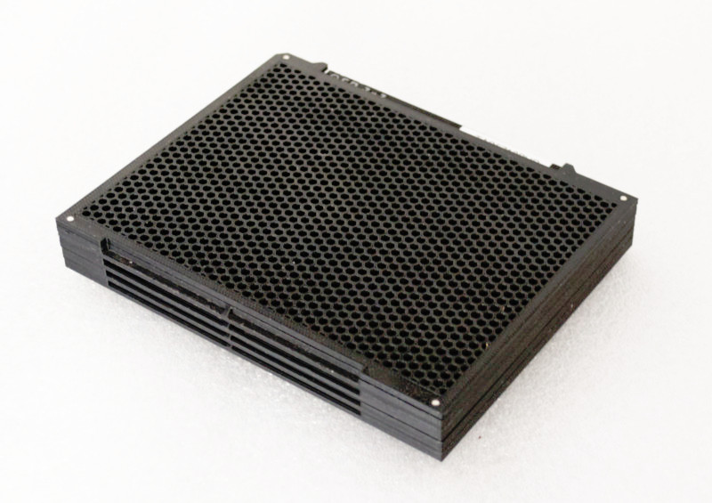
<p><strong>Note: the design has been updated: see </strong><a href="https://www.printables.com/model/173787-mini-tray-for-smd-components-version-2"><strong>https://www.printables.com/model/173787-mini-tray-for-smd-components-version-2</strong></a></p><p>The mini-tray was designed as an alternative to the standard JEDEC tray for semiconductors. It has the same width as a JEDEC tray, but its length is a third of that of a JEDEC tray. Thus, three mini-trays lined up have the same width/length dimensions as one JEDEC tray (the mini-tray is 0.85 mm thinner than a JEDEC tray).</p><p>JEDEC trays are optimized for purposes of mass production of electronics. The design of the mini-tray aims at small-scale production and storage of small series of components. Small pick-&-place have limited space for trays, sometimes only a single one. Mini-trays then allow for three times as many different tray-packaged components in a single project.</p><p>With JEDEC trays, an empty tray serves as a lid for a full tray. The reason for this choice is that the idea is that you stack up to 20 full trays. Each full tray is the lid for the tray below it. The large pick-&-place machines can unstack trays automatically, so you put the entire stack in the machine. So for storage and transport, using an empty tray as a lid for the topmost tray in the stack is a straightforward solution.</p><p>While mini-trays can stack, no pick-&-place machine to date can unstack them, nor is it likely that one ever will. You can still use an empty mini-tray as a lid for a full mini-tray, but for convenience there exists a mini-tray lid (or "cover"). The advantage is that the dedicated lid is thinner and that it does not obscure the tab of the tray: this tab is where you will put a label with the part number or description.</p><p>The mini-tray is also designed to have a magnet in each of the four corners, so that the lid snaps on the tray (and the mini-trays snap together). There is thus less risk that the components can "wiggle" out of their pockets while you are handling a stack. For storage, it is still recommended to also add a rubber band around a mini-tray with lid.</p><p>The relatively small size and the more common width/height ratio of the mini-tray makes it fit well in standard 127 mm x 152 mm anti-static sealed bags, together with a small bag with silica gel. These bags are available with grip-lock closing, and so they are reusable.</p><p>With regards to baking, only polycarbonate (PC) has a sufficient heat deflection temperature to create a "high-temperature" carrier, suitable for baking at 125 °C. 3D printed mini-trays of PETG, ABS or (especially) PLA must be considered "low-temperature carriers" (for use in drying cabinets with a baking temperature of 40 °C).</p><h3>Print instructions</h3><p>An ESD-safe plastic is highly recommended. These plastics may also be called <i>anti-static</i>, <i>dissipative</i> or <i>conductive</i>.</p><p>A mini-tray can be printed as a single part, but this requires that you add supports. The alternative is to print the frame and bottom part as separate objects, and glue them together. In this latter case, the design has a small rim in the "frame" (the part with the large rectangular hole in the middle), where the bottom part sinks into to just the right depth. The lid (or cover) is printed as a single piece, and it is universal for all mini-tray sizes. The model files are available both for a one piece print ("combined" in the filename) or for a two-piece print ("separate").</p><p>There are four holes in the corners of the mini-tray. These holes are specified in the design as 2.1 mm diameter. Due to the nature of 3D printing, they will typically come out a little smaller; the holes are intended for magnets of diameter 2 mm by 4 mm length (2 mm length for the lid).</p><p>The height of the mini-tray is 5.5 mm; however the <i>stacking height</i> is 4 mm. The bottom of the tray, with the honeycomb mesh, sinks 1.5 mm into a lowered top surface of the tray below it. That is, when two mini-trays are stacked together, the total height is 9.5 mm (5.5 + 4 mm).</p><p>The lowered surface mentioned above is the <i>platter</i>. The platter has the <i>pockets</i> in which the components sit. In the middle of a pocket is a raised square, called the <i>support</i>. The idea behind this support is that the pocket is deeper at the edges than in the middle, to avoid pressure in the relatively frail gull-wing leads of components. Obviously this is only relevant for components with gull-wing leads, but mini-trays for "no-lead" components also have a support in the middle of a pocket, to keep the design uniform.</p><p>The honeycomb mesh extends below the frame of the tray by 1.5 mm. This is the part that sinks into the top of the tray below it. However, the platter is lowered more than 1.5 mm from the top of the tray. There is a gap between the top of the platter and the bottom of the tray that covers it. This gap, or <i>separation</i>, is typically 0.5 mm, but it may be less for mini-trays designed for very thin components. The separation should always be less than the minimum height of the component that it is designed for, otherwise the components might wiggle out of their pockets.</p><p>The depth of a pocket (measured at the support, not at the edge) plus the separation (discussed above) determines the maximum thickness for a component in the mini-tray. These design parameters define the component thickness range that a tray is suitable for: <i>separation</i> → minimum thickness, <i>separation + pocket-depth</i> → maximum thickness. These are the parameters that you can play around with, when you are making your own mini-tray layouts.</p><p>Like the JEDEC trays, mini-trays have a chamfered corner to indicate orientation. The step sizes (from pocket to pocket) in the horizontal and vertical direction are also copied from JEDEC trays.</p><p>The body size in the table excludes the pins; it is the nominal size of the body as given in the datasheet for the component. In practice, pins for TQFP, LPQFP and other members of the QFP family, are 1 mm long.</p><figure class="table"><table><thead><tr><th>Type </th><th>Body size </th><th>Thickness </th><th>Columns </th><th>Rows </th><th>X-step </th><th>Y-step </th></tr></thead><tbody><tr><td>QFP</td><td>5x5</td><td>0.5 ~ 1.7</td><td>12</td><td>9</td><td>10.50</td><td>10.10</td></tr><tr><td>QFP</td><td>7x7</td><td>0.5 ~ 1.7</td><td>10</td><td>8</td><td>12.60</td><td>12.20</td></tr><tr><td>QFP</td><td>10x10</td><td>0.5 ~ 1.7</td><td>8</td><td>6</td><td>15.70</td><td>15.20</td></tr><tr><td>QFP</td><td>12x12</td><td>0.5 ~ 1.7</td><td>7</td><td>5</td><td>18.00</td><td>17.90</td></tr><tr><td>QFP</td><td>14x14</td><td>0.5 ~ 1.7</td><td>6</td><td>4</td><td>21.00</td><td>20.30</td></tr><tr><td>QFP</td><td>14x20</td><td>0.5 ~ 1.7</td><td>6</td><td>4</td><td>21.00</td><td>24.40</td></tr><tr><td>QFP</td><td>20x20</td><td>0.5 ~ 1.7</td><td>5</td><td>4</td><td>25.40</td><td>24.40</td></tr><tr><td>QFP</td><td>24x24</td><td>0.5 ~ 1.7</td><td>4</td><td>3</td><td>31.50</td><td>30.40</td></tr><tr><td>QFP</td><td>28x28</td><td>0.5 ~ 1.7</td><td>4</td><td>3</td><td>32.20</td><td>32.20</td></tr><tr><td>QFP</td><td>32x32</td><td>0.5 ~ 1.7</td><td>3</td><td>2</td><td>41.48</td><td>37.82</td></tr><tr><td>QFP</td><td>40x40</td><td>0.5 ~ 1.7</td><td>2</td><td>2</td><td>77.46</td><td>46.00</td></tr><tr><td>QFN</td><td>3x3</td><td>0.4 ~ 1.0</td><td>14</td><td>11</td><td>9.20</td><td>8.80</td></tr><tr><td>QFN</td><td>4x4</td><td>0.4 ~ 1.0</td><td>14</td><td>11</td><td>9.20</td><td>8.80</td></tr><tr><td>QFN</td><td>5x5</td><td>0.4 ~ 1.2</td><td>14</td><td>11</td><td>9.20</td><td>8.80</td></tr><tr><td>QFN</td><td>6x6</td><td>0.5 ~ 1.4</td><td>14</td><td>11</td><td>9.20</td><td>8.80</td></tr><tr><td>QFN</td><td>7x7</td><td>0.5 ~ 1.4</td><td>10</td><td>8</td><td>12.80</td><td>11.80</td></tr><tr><td>QFN</td><td>8x8</td><td>0.5 ~ 1.4</td><td>10</td><td>8</td><td>12.80</td><td>11.80</td></tr><tr><td>QFN</td><td>9x9</td><td>0.5 ~ 1.4</td><td>10</td><td>8</td><td>12.80</td><td>11.80</td></tr><tr><td>QFN</td><td>10x10</td><td>0.5 ~ 1.4</td><td>8</td><td>6</td><td>16.00</td><td>14.65</td></tr></tbody></table></figure><p><br> </p><p>There is a tab on the top edge of the mini-tray. By convention, this holds some texts on the type, size and features of the tray. I only put the package style and body size on it (where QFP is generic for TQFP, LPQFP, VQFP and others). The rest of the tab is then available for a label with the manufacturer part number, for example.</p><p>The design of the mini-tray is in <a href="http://www.openscad.org/">OpenSCAD</a>. Via the OpenSCAD "Customizer", you can select to print either the mini-tray or the lid. When choosing the mini-tray, you have the choice to either print it as a single part or as two parts, and you may optionally also print the label text separately. See the section "Printing recommendations" for more information. The OpenSCAD source file has quite a few options. There are pre-configured settings for common packages, but you can also make a mini-tray for a SOT223 package, for example.</p>
With this file you will be able to print mini-tray with your 3D printer. Click on the button and save the file on your computer to work, edit or customize your design. You can also find more 3D designs for printers on mini-tray.