Micrometer Stand
prusaprinters
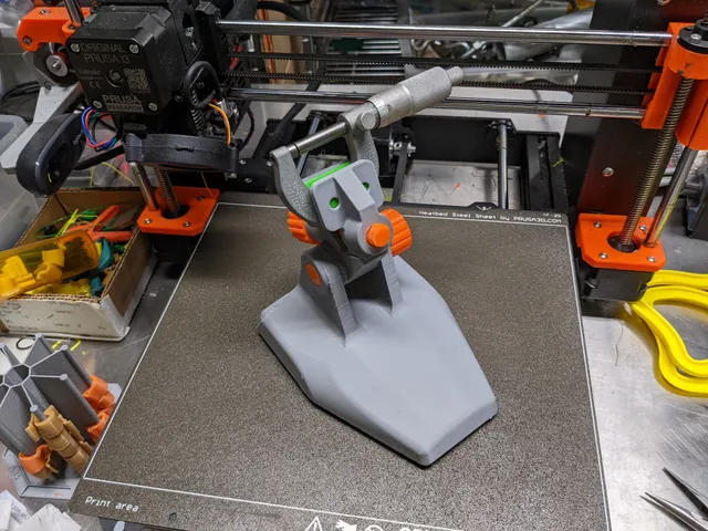
[Addendum May 1, 2022 : Added optional components for metal clamp screw. See below.] This is not a remix, but it is inspired by this print by Steven Nelson :https://www.instructables.com/3D-Printable-Micrometer-Stand/?utm_source=newsletter&utm_medium=emailI should state immediately that there is nothing wrong with Nelson's print, and I give him full credit for coming up with the idea. In fact, I would say that Nelson's version has the benefit of being simpler, and faster and easier to print (and of course it works!).My reasons for coming up with my own design are as follows :Testing an idea for “weighting” a printTrying for a fully 3D printed designTrying some ideas for creating and 3D printing threadsMaking a print with (separate) parts from different types of filamentHow does the cost of this stand compare to a ready-made micrometer stand? A cheap but serviceable micrometer stand purchased online can be had for about $21.00 (2021 price). The estimated cost of this printed stand (not including fill material for weight) is shown below. This is an approximate cost as it depends on the cost of filament.Base$1.65Clamps, Thread, FillPlug$0.74Screws$0.61Feet and Clamp Pads$0.40TOTAL$3.40So even allowing for higher filament cost and the cost of weight-fill material, the printed stand is considerably cheaper than a purchased one. Assembly[See the photos for an assembled version and an exploded view.]The print is designed so that the Base can be “weighted” by filling it with a heavy granular substance - the heavier the better. I used steel shot used for shot-blasting, but other possibilities are sand, steel or lead shot, salt, fine gravel (like aquarium gravel), plaster, cement, etc. The Base is filled via fill hole in the back, and then sealed using a screw-in FillPlug. Weighting the base is optional, but recommended. I found that the steel shot I used worked nicely, giving the base a “hefty” feel.Finish preparing the base by inserting the three Foot pieces on the bottom side. These should be a press fit, but use glue if desired.With the Base prepared, add the EarThread to the left hand “ear” of the Base. Note that the EarThread piece is slightly elliptical where it inserts (to prevent it from turning); the purpose of printing this piece separately is to enable optimal print orientation.If you are printing the ClampPad pieces, insert one into each clamp piece now. Similarity, insert the three Foot pieces into the bottom of the Base. All of these Flex pieces should be a firm press fit. Next, while holding the HolderBarrel in place, insert the EarScrew through the right hand “ear” and screw it into the EarThread. Be careful not to over-tighten the screw; loosen and tighten this screw to adjust the angle for holding the micrometer.Finally, assemble the ClampScrew by putting the two screw halves together and inserting them into the ClampScrewKnob. Note that the square hole in the knob is tapered, and the thread pieces should be inserted into the large part of the taper. Insert the screw assembly into the hole in the HolderBarrel, and while holding the HolderClamp piece in position, screw in the screw part of the way (leaving a gap between the pads to insert the micrometer).Using the micrometer stand is straightforward (see photos). Hold the micrometer frame between the pads and tighten the clamp screw to hold it in place. Use the right hand knob on the barrel screw to loosen the hold on the clamp assembly for adjustment, and then tighten it to hold the clamp assembly in position.Additional Comments on Printing ScrewAs you will notice, the two screws used in this print are printed in two different ways. The larger diameter screw prints vertically in one piece, and is strong enough when printed in this manner.The smaller diameter clamp screw, however, did not prove to be strong enough when printed in one piece vertically. I believe this is due both to the smaller diameter (less material = less strength), and also because prints are weakest where the layers come together. Splitting the screw in half makes it possible to print it so that the filament layers are oriented in a more favorable direction, as well as adding additional material strength. It is also worth noting that when the threads were designed in CAD, the points of the threads were “clipped” to make a kind of stub thread. I have found that these not only print better, but also work better in plastic without losing any significant strength.Print InstructionsThis is printed in PETG (mostly) on a textured plate. It might work in PLA but I have not tried this. Note that the part are mostly printed individually due to varying requirements for slightly different print settings. Note also that print orientation is important for all of the parts.I printed some parts in different colors just for contrast.Use the provided 3mf or gcode files to print in PETG. In general, the settings are :0.2mm layer heightperimeters = 2, 3, or 4 (depending on the part)15% rectilinear infillThe exceptions to the above are that the Foot and ClampPad are printed in Flex filament. The foot pieces could be printed in PETG if desired, but the pad pieces really need to be in a “soft” filament. If you do not have (or do not want) to print in Flex, then I recommend printing the feet in PETG and using stick-on furniture pads in place of the printed pads.Additional settings :HolderBarrel : uses adaptive layer height; some support under the curved section is recommendedBase : Perimeters = 4, 0% infill, and some (optional) supports for the curved “ears”Screws : Perimeters = 3, 15% rectilinear infill. I used variable layer height on the ClampScrew thread halves to make the knob insert smootherFeet and Clamp Pads : Flex, 0% infillAddendum May 1, 2022 : Added optional components for metal clamp screwUse these components for the clamp assembly if you prefer to use a metal screw for this. The parts are sized for either of these hex bolts:M8-1.25 X 75mm5/16"-18 X 3"You will need to tap the HolderClamp piece for the thread size you choose. The required pieces for this option all have “07” in the file name.Print the pieces in PETG using the 3mf or gcode files provided. In general :15% rectilinear infillperimeters = 3the HolderClamp piece has a modifier to increase the perimeters to 4 along the part to be threaded CADThe OnShape 3D CAD files for this are here :https://cad.onshape.com/documents/15ff23c34cd49f16fe7efec8/w/57ec9379aa9bf32cc9ec9ae4/e/906d7f1e1ac6d986a8ded21a
With this file you will be able to print Micrometer Stand with your 3D printer. Click on the button and save the file on your computer to work, edit or customize your design. You can also find more 3D designs for printers on Micrometer Stand.