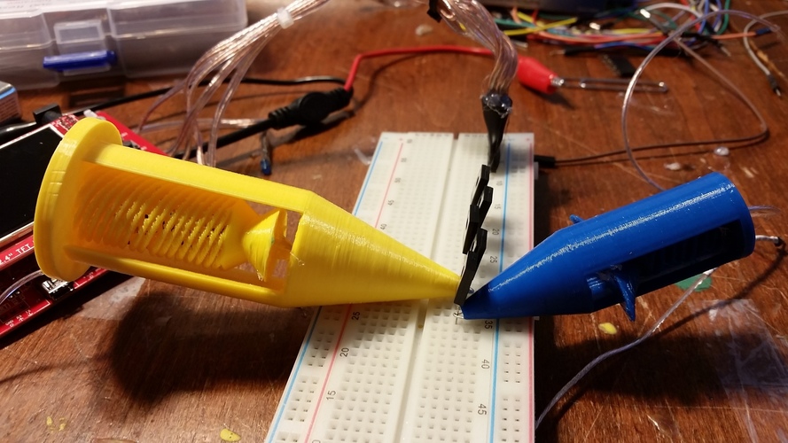
Mega-Mini-grabber Test Leads
pinshape
If you're an electronics hobbyist like me, oscilloscopes or multimeters are essential tools when it comes to designing or testing circuits. Low-cost standard probes can limit your ability to get accurate measurements on small or tight PCBs. Of course, there are specialized probes designed to fit into tight areas on a PCB. Typically found on an oscilloscope, mini-grabber test-leads offer an alternative to prong-based probes. Mini-grabbers use a small hook that can grip component leads without connecting to nearby components. This download includes the files needed to create large versions of mini-grabber test-leads (10cm length) with integrated springs. Yes, the spring is 3-D printed. As well as smaller, 6.8cm versions. Personally, I prefer the larger one because it fits my hand better. You'll need: - Needle-nose pliers - A large paperclip - Soldering equipment - Hot glue gun - Wire (preferably 22AWG) Print settings: Material: PLA Temperature: 190°C Support: None Raft: No Speed: 50mm/s Layer height: 0.2mm Infill: 10% or greater Instructions: Step 1: After printing, remove the six supports that hold up the main cone of the model as shown in Figure 1. Step 2: Flex the spring back and forth/up and down by moving the lab that extends out on both sides of the model. This tab should be connected to the spring only (Figure 2). Step 3: Bend the paperclip into a straight line. Cut it so it can fit inside the 3D-printed housing. At the end of the paperclip, use your pliers to create a small hook as shown in Figure 3. If you want to make a smaller hook for the smaller model, use an old lead from a resistor or diode. Step 4: Solder a wire about 18in long to the opposing end of the paperclip hook. If you used a resistor lead as a hook, solder the lead to the straightened paperclip and then the paperclip to the wire. Make sure to insulate your connections with heat-shrink. Step 5: Heat the hot glue gun while it's warming up. Slide the paperclip-hook and wire into the bottom of the test-lead, through the spring and hand tabs, until the very end of the printed housing. The hook should be flush with the aperture at the very end of the cone (Figure 4). Step 6: Glue the hook to the top of the spring as shown in Figure 5. Step 7 (Optional): Solder a male header to the opposing end of the wire and use alligator clips to connect the male header to any meter or machine. Step 8 (Optional): Add a 9M ohm resistor in parallel with a capacitor trimmer to the output of the test-lead to create a rudimentary 10X probe. Thanks for your time! -Frankie
With this file you will be able to print Mega-Mini-grabber Test Leads with your 3D printer. Click on the button and save the file on your computer to work, edit or customize your design. You can also find more 3D designs for printers on Mega-Mini-grabber Test Leads.
