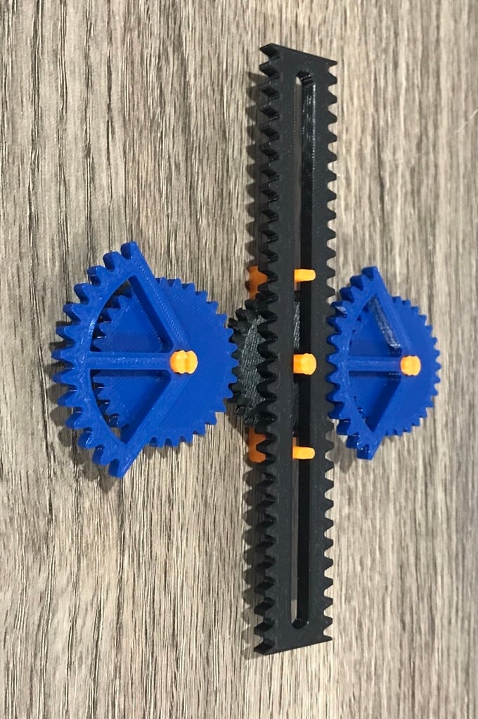
Mechanical Movement 123 - Rotation to Linear Motion
thingiverse
#Mechanical Movement 123 ###What is it? -This is a device that is designed to turn rotary motion into linear motion. It does this by having to drive gears engage with the rack at opposite times, in turn pulling the rack back and forth. The Description from the book 507 Mechanical Movements "Intended as a substitute for the crank. Reciprocating rectilinear motion of the double rack gives a continuous rotary motion to the center gear. The teeth on the rack act upon those of the two semi-circular toothed sectors, and the spur-gears attached to the sectors operate upon the center gear. The two stops on the rack shown by dotted lines are caught by the curved piece on the center gear, and lead the toothed sectors alternately into gear with the double rack." ###See http://507movements.com + Animation -You can preview the book from where this came from and an animation of its motion -http://507movements.com/mm_123.html - LINK TO MM123 -http://507movements.com - LINK TO HOMEPAGE If you enjoy anything mechanical this is an amazing book to refer to to discover all kinds of motions. The book "Five Hundred and Seven Mechanical Movements by Henry T. Brown." collection of 507 different mechanical motions. This comes from an era where there was not any computer controlled linkages, meaning it is from a very mechanical era and nothing like today world it encoders, servos, electric motors, and computer controlled movements. ###Asembly - TAKE A LOOK AT THE 507 MOVEMENTS PAGE WITH ANIMATION (THIS WILL HELP YOU GREATLY!) - ALSO LOOK AT THE PROVIDED IMAGE - This a fully 3D printable, not screws required Step 1 -Place the Drive Gear(The black gear) on the center pin of the Bracket (The orange part) Step 2 -Print 2 Gear Crank(The blue gears) and put them on the two outside pins. (The ones that are round with a slot down the middle) (The two oval shaped pins are to be used later) -The Gear Crank should be placed facing the same direction and should mesh with the Drive Gear (Again refer to the image above should you be confused) Step 3 -Place the Rack on the center pin, on top of the black Drive Gear and the two oval pins that were mentioned above. It should be centered evenly. If it is not it, may bottom out on either of the two oval pins cease motion ###Troubleshooting -The best help is to refer to the image and the 507 page and you might be able to figure it out without much hassle. PROBLEM The Rack and Pinon moves up until a point and binds up. SOLUTIONS 1 -Check that the Rack has not bottomed out on either of the two oval pins that guide it -Either of the two Gear Cranks might have a bur from support material that is colliding with the center Drive Gear. Sand the face down and ensue there is not burrs sticking out.
With this file you will be able to print Mechanical Movement 123 - Rotation to Linear Motion with your 3D printer. Click on the button and save the file on your computer to work, edit or customize your design. You can also find more 3D designs for printers on Mechanical Movement 123 - Rotation to Linear Motion.
