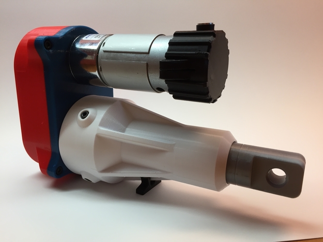
Mechanical Actuator
pinshape
It appears that you've provided a detailed guide for assembling a gear-driven system, specifically a 3-stage gearbox. The guide includes step-by-step instructions on how to assemble the various components of the gearbox, such as the gear motor, drive gears, and screw. Here are some key points from the guide: 1. Bolt the gear motor onto the main plate. 2. Bolt the drive gear onto the motor's shaft. 3. Install stage 2 and 3 gears. 4. Bolt the gear on the screw. 5. Bolt the back cover onto the main plate. 6. Screw the actuator rod onto the drive screw. 7. Slide the guide housing onto the drive screw, aligning the anti-rotation keyway and bolt it on. The guide also mentions that using lithium grease on the gears, bearings, and screw can help with longevity and capacity. In terms of required fasteners and purchased components, the guide lists: * 1/8” diameter dowel pins (12x) * M3x.5 socket head cap screws (21x) * DC gear motor (PN: A14040300UX0970, manufactured by Uxcell, voltage: 24vdc/1amp, RPM: 1000) * Thread inserts (M3x.5mm thread, 5.6mm od x 3.8mm lg. brass, QTY: 16) The guide also provides links to purchase the DC gear motor and thread inserts. Finally, the guide mentions that you can find a motor controller and housing designed for it under a previous project on Pinshape. If you'd like me to elaborate on any of these points or provide further clarification, please let me know!
With this file you will be able to print Mechanical Actuator with your 3D printer. Click on the button and save the file on your computer to work, edit or customize your design. You can also find more 3D designs for printers on Mechanical Actuator.
