Maxwell Capacitor Boostcap 16v module balance board housing
prusaprinters
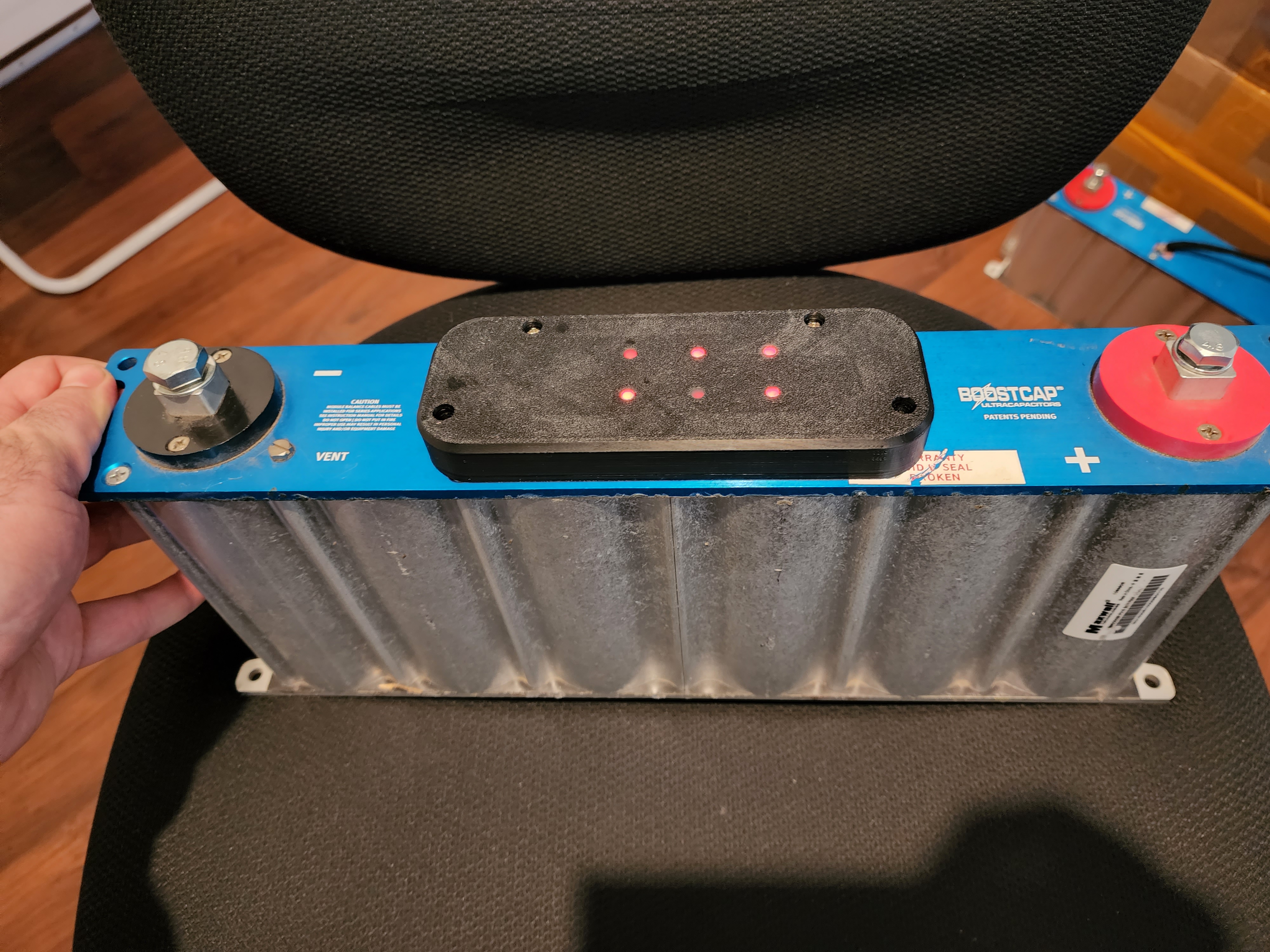
<p>Suits 77x47mm PCB designs.</p><p>You will need an additional 3 m3x10 screws, 2 m3 heat set inserts, and some hot glue.</p><p>Two cover designs as one has holes that can be filled with hot glue to allow the balance LEDs to shine through the cover.</p><p>It is probably best to print in ASA/ABS anything else I think is an overkill or might get a bit melty.</p><p>To install </p><ul><li>Install the two heat sets to the cover base from the top.</li><li>Mount the base to the capacitor bank with one m3x10 screw in the center mounting hole making sure the other holes line up.</li><li>Test fit the balance board with the connector furthest from where the balance leads come out of the capacitor housing, solder and heat shrink on the new balance leads/connector and run them underneath the balance board.</li><li>Put some hot glue to hold the balance cables secure and from rubbing on the PCB, also put a little on the underside of the bord to hold it in place before the top cover is fitted, once the top cover is fitted it will calmp the bord in place.</li><li>If using the cover with holes place it face down on a silicone mat and fill the holes with hot glue, once it has cooled remove it from the mat.</li><li>Fit the cover top to the lower section with 2 m3x10 into the heat sets and two original screws in the holes that mount into the capacitor housing.</li></ul>
With this file you will be able to print Maxwell Capacitor Boostcap 16v module balance board housing with your 3D printer. Click on the button and save the file on your computer to work, edit or customize your design. You can also find more 3D designs for printers on Maxwell Capacitor Boostcap 16v module balance board housing.