Mammoth Prusa MK3 Einsy Case Replacement
prusaprinters
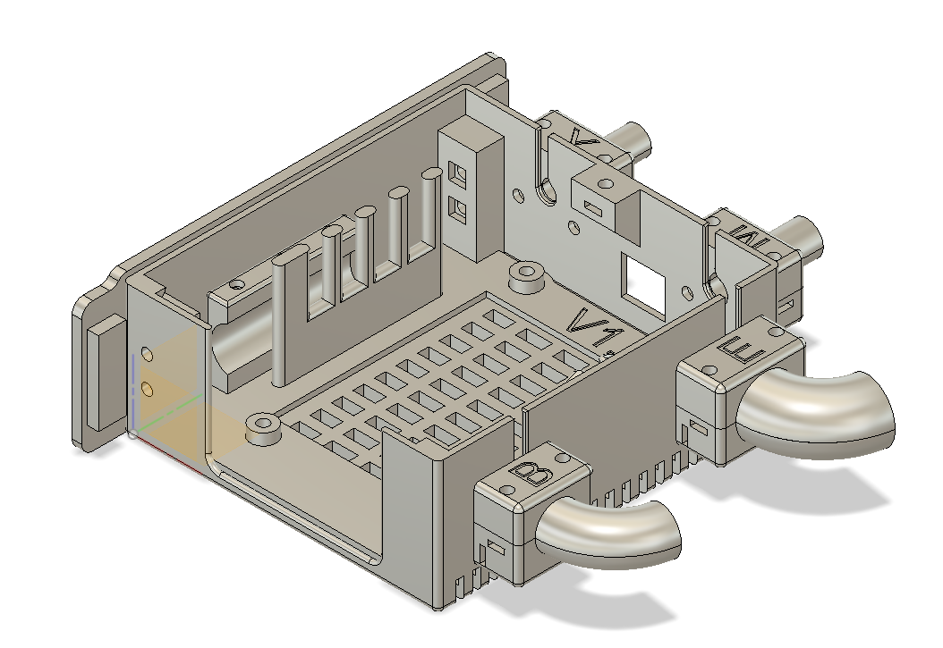
<p><strong>Problems I am attempting to solve:</strong></p><ul><li>Original Case was extremely cramped.</li><li>Original Case was a pain to mount to the frame</li><li>Original Case didn't have very good wire management</li><li>Original Case was a pain to get into</li></ul><p><strong>Design Goals</strong></p><ul><li>Has to print without supports*.</li><li>Easy to Mount to the Frame.</li><li>Better wire Management</li><li>Uses Threaded Metal Inserts or Square M3 nuts, or mix as needed</li><li>Easy to get into (The less screws the better)</li><li>Modular so parts of it can be upgraded if needed without having to reprint everything</li><li>No Zip Ties</li></ul><p><i>* - Almost made this goal. The only part that really needs supports is the Back Cover.</i></p><p>All parts were designed in Autodesk Fusion 360.</p><p>I printed mine in Prusament Galaxy Black PLA, with a layer height of .3 on my Prusa Mini.</p><p>There are 16 parts to print.</p><ul><li>I pretty much use the default settings in Prusa Slicer 2.3 with the exception of the Layer height, which I believe the default profiles don't have a .3.<br> </li><li>The case is large and it can Warp when printing, so you might need to make some adjustments to your print settings. <br> </li><li><strong>Nothing needs supports. (Except the Back Cover)</strong><br> </li><li>I print all the Strain Relief parts with the letter facing UP. Half will be upside down when added to the slicer so you will need to flip them.<br> </li><li>The Cover needs to be printed flat side down. When you add it to the slicer, it will be upside down.<br> </li><li>Top Bracket is upside down when added to the slicer.<br> </li><li><strong>Recommend setting infill for the Wiring Guide Insert to 30% for additional strength</strong></li></ul><p><strong>NOTE! All Screws are Button Head.</strong></p><p>I used the following hardware:</p><p>M3x6 for Strain Reliefs holding to case<br>M3x10 for the Mount Screw<br>M3x10 for the Cover Screw<br>M3x12 for the PCB Mount Screws<br>M3x14 for the Brackets<br>M3x16 for the Strain Relief Tops</p><p>Number of screws you'll need:<br><br>M3x6 x 8<br>M3x10 x 2<br>M3x12 x 4<br>M3x14 x 4<br>M3x16 x 8</p><p>M3 Square Nuts or M3 Metal Inserts x 26.</p><p><strong>EDIT</strong>: Some clarification on the Nuts and/or Inserts needed. Here is what I use:</p><ul><li>1 Metal Insert in the Frame Mount.</li><li>1 Metal Insert in the Top of the Case where the cover screws on.</li><li>4 Square Nuts on the inside of the case for the top and bottom brackets as it's easier to install that way.</li><li>4 Metal Inserts in the bottom of the case to hold the PCB in.</li><li>16 Metal Inserts (4 Each) for 4 Strain Reliefs.</li></ul><p>If you don't want to use Metal Inserts Square nuts will work just fine.</p><p>If you use Metal Inserts I recommend the M3 that are brass, tapered and 4mm length.</p><p><strong>The recommended order of assembly is:</strong></p><ol><li>Attach the Mounting Plate to the Frame of the Prusa MK3. It should only line up with one set of 4 holes.<br> </li><li>Attach the Upper and Lower brackets to the Case. The Lower bracket only has 2 holes in it. The Upper bracket has 3 holes in it.<br> </li><li>Attach the bottom halves of the restraints X, E, and B, in that order.<br> </li><li>Insert the Wiring Guide Insert <br> </li><li>Screw down the Einsy PCB to the case<br> </li><li>Run the wires to the PCB as you would normally do<br> </li><li>Route the wires through the appropriate holes and then screw down the stop strain reliefs<br> </li></ol><p><strong>Additional Notes:</strong></p><p>If you have the MMU, the case is a little more challenging to get into because of the length of the wires to the MMU. I would recommend trimming down the sleeve to help with the wiring inside the box.</p><p>For mine, I used press in inserts for 99% of the parts, but I also designed it to use 100% of the square trapped nuts. For the top and bottom brackets I used the square nuts as it was easy to get to those.</p><p>The 3 extra holes on the Wire Guide Insert are for additional mounting of items if needed. They were put in as a “Just in case” measure, but I don't really have a use for them currently.</p><p><strong>Credits:</strong></p><p>Mammoth Image taken from here:</p><p><a href="https://svgsilh.com/image/45726.html">https://svgsilh.com/image/45726.html</a></p><p>Hope you like it! Please let me know what you think and if you have any suggestions for improvements.<br><br><strong>Version History</strong></p><p><strong>February 26th, 2022</strong></p><p>Parts Revised:</p><ul><li>Main Case</li><li>Wire Guide</li></ul><p>The tolerances for inserting the Raspberry Pi Zero 2 were too tight and could cause damage to the Pi if it was forced in. I've added a notch to the case to give it plenty of clearance now. If you have already printed the case you could modify it with a Dremel or other cutting tool to give it a little more clearance.</p><p>I made a minor tweak to the Wire Guide Insert. The Upper Left hole was too tight for my liking, so I enlarged it to match the rest of the holes. </p><p><strong>February 17th, 2022</strong></p><p>Parts Revised:</p><ul><li>Wire Guide</li></ul><p>There was an error in the model that I didn't catch. Part of the base wasn't extruded in Fusion360. Version 1.3 is still usable, but it's not what I had intended, so here is version 1.4 of that part. </p><p><strong>February 3rd, 2022</strong></p><p>Parts Revised:</p><ul><li>Wire Guide</li><li>Case</li></ul><p>New Parts Added:</p><ul><li>Back Cover</li><li>Back Cover Latch</li></ul><p>The Wire Guide and Case were modified to support the Pi Zero 2. The back cover has a lip on the bottom edge that fits into the new case. You then use the latch at the top to hold it in place. The longer edge of the clip goes down.</p><p><strong>January 27th, 2022</strong></p><p>Parts Revised:</p><ul><li>Wire Guide</li><li>Bed Strain Relief</li><li>Extruder Strain Relief</li></ul><p>I modified the Wire Guide ribbon cable guide to be thicker on the back side (side closest to the case) and removed enough of it to access the Bed Strain Relief screws so you don't have to remove the Einsy Board or Wire Guide to replace the Bed Strain Relief.</p><p>I modified the Bed Strain Relief to curve upwards like the Extruder Strain Relief in order to make sure the Bed Heater Wires don't come in contact with the frame. </p><p>Minor modification to the Extruder Strain Relief by rounding the inside edge. If you've already printed and installed the current version you should be fine. I just don't like “sharp” edges along any wire paths.</p><p><strong>January 16th, 2022</strong></p><p>Parts Revised:</p><ul><li>Mounting Plate</li><li>Extruder Strain Relief</li></ul><p>Revised the Mounting Plate by making the case mounting hole go all the way through the part so that if you accidently used too long of a screw, the frame would stop you from breaking the part.</p><p>Changed the Extruder Strain Relief to curve upwards to help keep the wires off the bed.</p>
With this file you will be able to print Mammoth Prusa MK3 Einsy Case Replacement with your 3D printer. Click on the button and save the file on your computer to work, edit or customize your design. You can also find more 3D designs for printers on Mammoth Prusa MK3 Einsy Case Replacement.