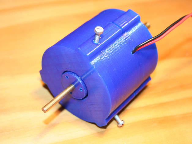
M-Probe: 3D CNC Touch Probe - Fully adjustable
thingiverse
M-Probe ("Marko") Probe 3D Touch Probe for CNC\nIf you're unfamiliar with 3D touch probes, check out online resources for more information.\nThis video demonstrates how to find a circle's center: https://www.youtube.com/watch?v=_ZDlyLI_jbc \nI own a self-made CNC machine and a 3D probe is an essential tool for aligning or measuring parts on the CNC table.\nProfessional probes are priced in the K$ range, while good semi-pro options cost a few hundred dollars.\nThe designs are largely similar (old patent), but precision and durability are key.\nMost precise 3D CNC probes require a thread machine for production.\nOnly by doing so can all components be perfectly aligned, ensuring precision from the start.\nIf you mill or print it... you'll encounter problems... until now!\nHave fun building your own M-Probe!\nMarko Hoepken\nHow I Designed This Project\nAbout My Project\n My idea behind this project was:\n"Create a probe with a 'low-end' printer, but still achieve maximum precision."\nPrecision means fully adjustable in all axes to compensate for production imperfections.\nOn the printing side, all parts must be easy to print flat without overhangs.\nThis led to my "M-Probe" design (Marko - Probe).\nThe center component is fully floating on rubber and can be adjusted in all axes.\nI built only one unit without any changes. After 1 hour of adjustment, I achieved a precision of +/- 50um.\nI didn't write extensive documentation, but took plenty of photos during the build process.\nIf you have a basic understanding of how probes work, you'll be able to replicate this project.\nThe attached photos (37 in the zip package) should provide all necessary information.\nThe Zip file contains all design files (Design Spark Mechanical = FREE), STL for printing, and 37 photos of my build process.\nThe ready-to-print parts are located in the "parts" subfolder:\nbody_bottom.stl\nbody_top.stl\nprobe_ball_holder.stl\nprobe_bottom.stl\nprobe_top.stl\nIf you want more details or modify the design, download Design Spark Mechanical from http://www.rs-online.com/designspark/electronics/eng/page/mechanical and open the file "3D Probe.rsdoc"\n\n \n \n Custom Section\nHints for Building and Adjustment\n Some notes for makers:\nSCREWS, HOLES, THREADS\nAll screws are 3mm in diameter. All mounts have 3mm holes.\nDrill 3mm after printing to ensure a smooth fit.\nOn the thread side, use a drill bit of 2.5mm. I recommend re-drilling with 2.5 (cool while drilling!)\nUse a thread cutter to create M3 threads.\nI cool all parts with compressed air before assembly.\n\nRepeat this process until you achieve perfect alignment.\nCheck and improve your settings using http://www.craftycnc.com/probe-it-wizard-mach3 \ nIMPORTANT:\nAll alignment can be done within a range of ~2-4mm.\nIt's recommended to create a minimum pressure on the silicon hose.\nIf they are too loose, all components will become "fussy". Make sure some default pressure is applied to each screw.
With this file you will be able to print M-Probe: 3D CNC Touch Probe - Fully adjustable with your 3D printer. Click on the button and save the file on your computer to work, edit or customize your design. You can also find more 3D designs for printers on M-Probe: 3D CNC Touch Probe - Fully adjustable.
