M-Bot, 400x300x400mm Build Volume, 3 leadscrews, Titan Aero direct drive, IR-bed leveling
prusaprinters
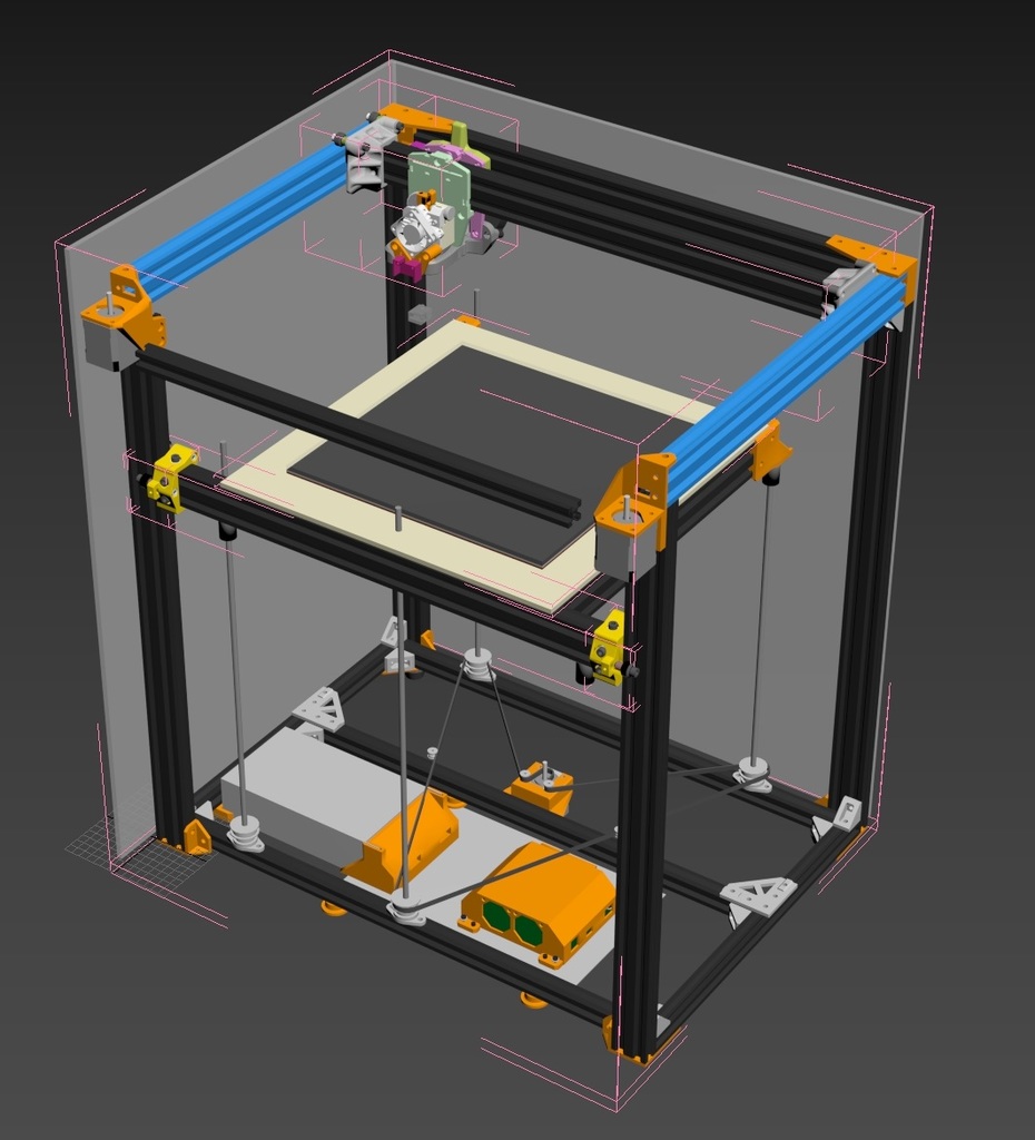
<h3>Most of the below is just for historical record. This is a deprecated design. See links below.</h3> <p>M-bot v.2; <a href="https://www.thingiverse.com/thing:3045974">https://www.thingiverse.com/thing:3045974</a></p> <p>M-bot v.3; <a href="https://www.thingiverse.com/thing:3134348">https://www.thingiverse.com/thing:3134348</a></p> <p>M-bot v.3.5; <a href="https://www.thingiverse.com/thing:3889891">https://www.thingiverse.com/thing:3889891</a></p> <p>So far this is just a mockup, to determine extrusion lengths, and to accommodate the claimed features.</p> <p>While there is two effectors on the X axis, I plan to start out with just one, and to figure out how the belts are run, in order to install a second.</p> <p>I'll be using KFL08 Shaft supports, for the three leadscrews, and I'll be installing them in different locations to the design by oeyhaga.</p> <p>Much of my BOM is determined by the spare parts I have in stock already, and primarily it's the RobotDigg parts that I needed to purchase to get underway.</p> <p>The hardware list is likely not accurate, since I'm removing quite a few parts from the original D-bot, such as the Z-end stop, which I'm replacing with an IR sensor, and the spool mount, as I have a rack above my existing printers that serves that purpose well.</p> <p>/edit</p> <p>Some notes on the STL files uploaded so far: These are the parts required to install the 3 leadscrews. Any prospective assemblers will need to pay attention to how I have constructed my bottom frame, with the two wide 2020 extrusions, set back 20mm from the front and back of the bot.</p> <p>The models were printed in solid ABS, using a 0.8mm volcano nozzle with 0.25mm layers. As a result they are much sturdier than equivalent PLA or PET-G prints might be. Good luck!</p> <p>/edit2</p> <p>I've added two new photos to show my progress so far. The overview photo shows where I am at, approximately. I've wired together some of the electronics, but left everything with stock wire length because I'm not too sure how I'll arrange it all yet. The XY belts are attached, and pretty tight, though I'm not sure if they're tight enough. Endstops are in place.</p> <p>/edit3</p> <p>I am going to be starting out with this printer, using a bowden extruder of my own design. It's a simple, non-geared, clamp model, that I made using parts I had lying around, to drive the Volcano on my Kossel XL. It pushes filament quickly and reliably, and is cheap to make. You can find it here; <a href="https://www.thingiverse.com/thing:2423115">https://www.thingiverse.com/thing:2423115</a></p> <p>/edit4.1</p> <p>I've got the Z axis moving cleanly, and accurately. Here is the parts list for this component:</p> <p>For large (400x300mm XY build area) 1524mm GT2 belt</p> <p>For regular D-bot 1200mm GT2 belt</p> <ul> <li>3x anti-backlash nuts</li> <li>3x Single start 8mm leadscrews</li> <li>3x 40 tooth pulleys 8mm ID</li> <li>3x pillow bearings 8mm ID</li> <li>6x M5x8mm</li> <li>6x t-nuts (pre-or-post install as needed)</li> </ul> <p>Bearing tensioners (see note):</p> <ul> <li>2x M5x40mm</li> <li>4x t-nuts (pre-or-post install as needed)</li> <li>6x M5 (OD <10mm) washer</li> <li>2x M5 nuts</li> <li>2x ID 5mm OD 14mm bearings</li> <li>4x ID 5mm OD 16mm bearings</li> </ul> <p>Z motor mount:</p> <ul> <li>8x M3 washer</li> <li>2x M3x10mm</li> <li>2x M3x25mm</li> <li>4x F623ZZ Flange Bearings</li> <li>1x 20 tooth pulley 5mm ID</li> <li>1x 0.9 step angle 48mm (1.68A) 5mm shaft Nema17* &**</li> <li>2x M5x10mm</li> <li>2x M5 washer</li> <li>2x t-nuts (pre-or-post install as needed)</li> </ul> <p>*Steps per MM 3200, maximum MM/min 400, mA 1680</p> <p>**A note on the above. I'm now using a 60mm Nema17 for the Z axis, and while 400MM/min is possible, there was a few moments where the bed didn't want to move smoothly with the older motor, so I think slower speeds might be better.</p> <p>Printed components:</p> <p>1x z-motor-mount-print</p> <p>1x backlash-nut-mount-2040-rear</p> <p>2x backlash-nut-mount-2040-print-x2</p> <p>I don't have time to write instructions yet, but the most recent pictures I've put up show the final arrangement. The main complication, other than fitting, is to ensure that the leadscrews are installed parallel to the wheel guides. The way I did this (and it was sufficient), was to use a tape measure, to make sure that the top and bottom of the leadscrew were the same distance from the 2040 extrusions to within 0.5mm.</p> <p>Note on bearing tensioners:</p> <p>Assemble as following:</p> <p>Place onto the bolt, towards the head; Large bearing, then washer, then small bearing, then washer, then large bearing, then washer, then M5 nut, fastened.</p> <p>Then place a T nut around 10mm down the threads. And another T nut on the 2020 extrusion, and fix bolt to extrusion.</p> <p>/edit5</p> <p>I got my beard stuck in the pulley over the X and Y motors while peering at prints so I designed and printed motor caps that are easy to print and install.</p> <p>/edit6</p> <p>I've added parts for the linear rod Titan Aero mount, which let me get acceleration up to 2400, with acceptable rigidity. I'll be adding more stiffness to the design for the rod ends. This is where I'm seeing the most vibration (only in short jerky infill moves) when I put acceleration above 4800. Feel free to ask about the parts required, but this is very much a beta setup.</p> <p>I've also uploaded an idler arm for the Titan, to allow the use of a grooved bearing I had on hand. Parts required; cap head M4x8mm bolt, bearing spacer / washer (I'm using an m5, but an m4 will work), OD10mm,ID5mm,4mm thick bearing (for motor shaft).</p> <p>The idler arm is a remix of the design by Miklos Hejjas; <a href="https://grabcad.com/library/titan-aero-extruder-assembly-1">https://grabcad.com/library/titan-aero-extruder-assembly-1</a></p> <p>/edit7</p> <p>This will be the last major update for this printer, as I am now building a second CoreXY printer, based on the lessons learned with this one. It will be listed separately as the M-BOT v2.</p> <p>The main changes from edit6 are; I've deleted the linear rods, and returned to using a 2040 extrusion for the main moving components. The linear rods had far too much deflection for this scale of printer, and I should've known better ... should've done more research.</p> <p>I've also updated each printed corner piece / carriage to have no part outside the extents of the extrusions, so that an enclosure can be easily fitted. This is a very enclosure friendly design.</p> <p>Additionally, the printer could easily be constructed using these dimensions with a 400x300mm bed in mind, so I'll be updating the title to reflect that.</p> <p>The effector I've selected is the AC-Bot Carriage, and I've had to make some modifications to it, to work with the components I had available. I'll also upload those.</p> <p>I'll likely replace this text at some point with rough instructions, and put the updates in the files as a changelog.</p> Category: 3D Printers
With this file you will be able to print M-Bot, 400x300x400mm Build Volume, 3 leadscrews, Titan Aero direct drive, IR-bed leveling with your 3D printer. Click on the button and save the file on your computer to work, edit or customize your design. You can also find more 3D designs for printers on M-Bot, 400x300x400mm Build Volume, 3 leadscrews, Titan Aero direct drive, IR-bed leveling.