Lulzbot Taz 6 leadscrew indicator
thingiverse
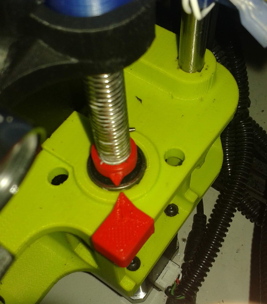
Align your X-Axis with ease using simple indicators that ensure a perfect lineup.\r\n\r\nSecure the indicators[1] in place - verify the one on the leadscrew is high enough to avoid collision with the fixed indicator. Don't tighten the one on the leadscrew yet.\r\n\r\nStraighten out your X-Axis (this handy guide will help: https://www.thingiverse.com/thing:2992448) and adjust each leadscrew indicator so its pointer lines up precisely with the fixed indicator.\r\n\r\nYou can rely on a Mk I Eyeball to check the axis alignment whenever needed, using a useful technique like jogging Z at 0.1mm per click on the control knob (a hint: this method is especially helpful).\r\n\r\n[1] - To fit these indicators, you'll need to partially remove the lead screws; I wouldn't have done it if I hadn't encountered a cracked connector (the giveaway was a ticking sound on Z moves). Lulzbot uses locktite or similar on the connector grub screws, and I had to apply heat to loosen them.\r\n\r\nThe process is straightforward:\r\n\r\n1. Jog the X beam to its middle point within the Z travel range.\r\n2. Release the leadscrew connectors (just from the leadscrew; you can leave them attached to the motors).\r\n3. Remove the printed top Z plates from the frame.\r\n4. Lift the X-Axis so the bottom of the leadscrews is exposed and remove the bottom bearings.\r\n5. Install the leadscrew indicators onto the leadscrews (I'd fit the M2 clamp screws & nuts beforehand).\r\n\r\nAs all good manuals advise, reassembly is simply the reverse of disassembly.
With this file you will be able to print Lulzbot Taz 6 leadscrew indicator with your 3D printer. Click on the button and save the file on your computer to work, edit or customize your design. You can also find more 3D designs for printers on Lulzbot Taz 6 leadscrew indicator.